| CPC F21V 29/74 (2015.01) [F21L 4/00 (2013.01); F21V 29/508 (2015.01); F21V 29/60 (2015.01); F21V 29/71 (2015.01); H02J 7/0042 (2013.01); F21W 2131/1005 (2013.01); H02J 7/0063 (2013.01)] | 41 Claims |

|
1. A charger for an electrical device, the charger comprising:
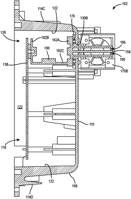
a housing having a plurality of walls defining an interior cavity, the housing including an inner housing member connected to one of the walls and separating a housing volume of the housing into a first interior cavity and a second interior cavity;
one or more openings formed in the housing, the one or more openings fluidly communicating the interior cavity with an exterior of the charger; and
a heat sink at least partially disposed in the housing and operable to dissipate heat produced in the housing, a first portion of the heat sink positioned within the interior cavity, a second portion of the heat sink positioned in the one or more openings such that the heat sink is at least partially exposed to the exterior, the heat sink in heat transfer relationship with components of charger electronics of the charger.
|