| CPC F16L 37/23 (2013.01) | 9 Claims |

|
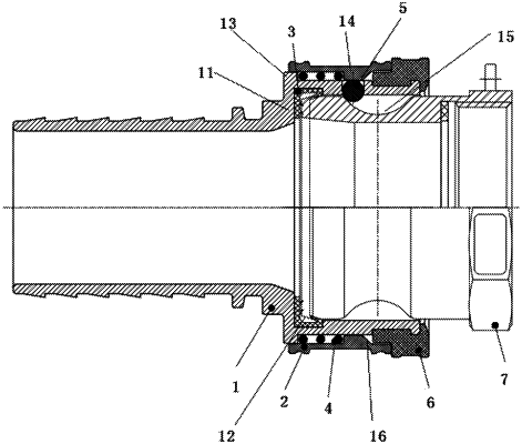
1. A quick insertion locking connector, comprising a female connector and a male connector inserted into the female connector; wherein the female connector comprises a female connector body, a receiving joint arranged at one end of the female connector body, a sliding sleeve and a protective sleeve which sleeve an outer wall of the receiving joint in sequence, and a sealing ring arranged on an inner wall of the receiving joint,
a plurality of limiting holes are circumferentially formed in a side wall of the receiving joint, limiting elements are arranged in the plurality of limiting holes, and the plurality of limiting holes are capable of limiting the limiting elements from being inwardly separated from the limiting holes,
a first boss is provided on the outer wall of the receiving joint, a second boss is provided on an inner wall of the sliding sleeve, the sliding sleeve sleeves the first boss, the second boss abuts against the outer wall of the receiving joint, such that the first boss, the second boss, the sliding sleeve and the receiving joint form a mounting cavity for receiving an elastic element in a compressed state,
a recess and a boss base extending along the inside of the receiving joint are formed in the inner wall of the receiving joint, the sealing ring is arranged on the boss base, extends on the boss base along a radial direction of the receiving joint, and extends into the recess along an axial direction perpendicular to the radial direction of the receiving joint, the male connector comprises a male connector body, a plurality of limiting grooves are circumferentially formed in an outer wall of the male connector body;
when the male connector body is inserted into the receiving joint, the second boss slides to the limiting holes and presses the limiting elements into the limiting grooves; and when the second boss slides away from the limiting holes, the limiting elements are capable of being separated from the limiting grooves; and the male connector body is configured for being inserted into the receiving joint and abutting against a part of the sealing ring located on the boss base and a part of the sealing ring located in the recess, wherein the part of the sealing ring located on the boss base is configured for abutting against and sealing an end surface of the female connector, and the part of the sealing ring located in the recess is configured for abutting against and sealing a side surface of the male connector.
|