| CPC F16L 37/082 (2013.01) [F16L 17/04 (2013.01); F16L 21/005 (2013.01); F16L 21/065 (2013.01)] | 20 Claims |

|
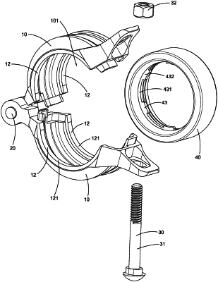
1. A combination of a pipe element and a pipe element coupler for coupling two pipe elements each having a groove and a groove circumference at a bottom of the groove, wherein the pipe element coupler comprises:
two coupling members arranged to be coupled end-to-end to define an inner cavity, wherein each of said coupling members comprises two engaging keys extended from two sides thereof respectively and two engaging surfaces defined at said engaging keys respectively, wherein each of said engaging keys has an engaging surface having varying radiuses of curvature;
a gasket disposed in said coupling members within said inner cavity;
a pivotally connecting element pivotally connecting said two coupling members; and
a fastening element is mounted at said coupling members to move said coupling members between a preassembled position and an assembled position, wherein each of said engaging surfaces has a proximate end point adjacent to said pivotally connecting element and a distal end point adjacent to said fastening element, wherein said varying radiuses of curvatures of each of said engaging surface are gradually increased from said proximate end point to said distal end point, so as to define a gap gradually increased from said proximate end point to said distal end point between each of said engaging surfaces and the corresponding groove circumference of each of the pipe elements when said coupling members are at said preassembled position in which said coupling members are arranged for encircling the pipe element to align said engaging keys with the grooves respectively, wherein at said assembled position, said coupling members are fastened with each other for engaging said engaging keys with the grooves respectively in such a manner that each of said engaging keys is deformed to self-adjust a curvature thereof and reduce the gap for matching with a curvature of the groove circumference so as to tightly couple said coupling members at the pipe elements to couple the pipe elements end-to-end; wherein each of the pipe elements has an enlarged coupling end portion, wherein said gasket comprises a plurality of protrusions which are spaced apart from each other, wherein said protrusions are adapted for being sandwiched between the two enlarged coupling end portions of the pipe elements; each of said engaging surfaces defines a logarithmic spiral curve having an equation of ρ=eθ, wherein ρ denotes a radius of curvature of the engaging surface, θ denotes a center angle between said distal end point and said proximate end point, and Sp denotes a dimension of the pipe element wherein the dimension of the pipe element is a diameter of a body portion of the pipe element;
wherein when Sρ=60.3 mm, θ has a range of 0-169.88°;
wherein when Sρ=73.0 mm, θ has a range of 0-170.67°;
wherein when Sρ=76.1 mm, θ has a range of 0-171.23°;
wherein when Sρ=88.9 mm, θ has a range of 0-172.46°;
wherein when Sρ=108.0 mm, θ has a range of 0-173.53°;
wherein when Sρ=114.3 mm, θ has a range of 0-173.92°;
wherein when Sρ=133.0 mm, θ has a range of 0-174.84°;
wherein when Sρ=139.7 mm, θ has a range of 0-175.02°;
wherein when Sρ=141.3 mm, θ has a range of 0-175.05°;
wherein when Sρ=159.0 mm, θ has a range of 0-175.57°;
wherein when Sρ=165.1 mm, θ has a range of 0-175.68°;
wherein when Sρ=168.3 mm, θ has a range of 0-175.76°;
wherein when Sρ=216.3 mm, θ has a range of 0-175.42°;
wherein when Sρ=219.1 mm, θ has a range of 0-175.47°.
|