| CPC F04D 29/281 (2013.01) [D06F 58/20 (2013.01); F04D 17/08 (2013.01); F04D 29/4226 (2013.01)] | 10 Claims |

|
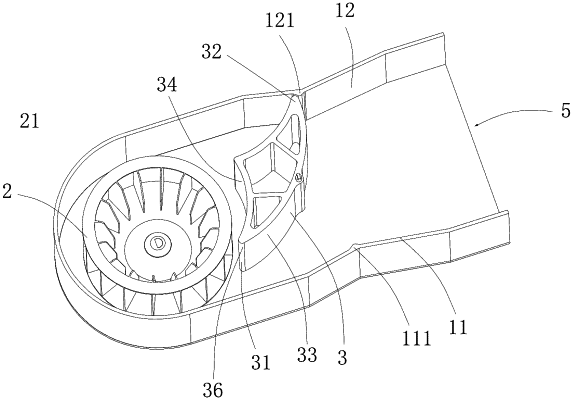
1. A centrifugal fan, comprising:
a housing,
a driving mechanism,
an impeller arranged in the housing, and
a volute tongue arranged in the housing and having a rotating shaft,
wherein the housing is provided with an air inlet and an air outlet, the driving mechanism is connected to the volute tongue via the rotating shaft and is capable of driving the volute tongue to rotate between a first limit position and a second limit position, and the volute tongue comprises a first volute tongue portion and a second volute tongue portion;
wherein the volute tongue has a periphery including a first curve surface, a second curve surface connected to the first curve surface at a first side edge, and a third curve surface connected to the first curve surface at a second side edge and to the second curve surface at a third side edge;
wherein the first side edge and the second side edge are positioned on opposite sides of the first curve surface, the third side edge is positioned between the first curve surface and the impeller, and the rotating shaft is positioned adjacent to the middle of the first curve surface;
wherein the first curve surface protrudes away from the impeller and both the second curve surface and the third curve surface protrude towards the first curve surface;
wherein the impeller is arranged to be capable of suctioning air into the housing from the air inlet when rotating, and the volute tongue is arranged to be capable of cutting the air blown from the impeller and guiding the air to the air outlet when the volute tongue is in the first limit position and the impeller is rotating in a forward direction; and wherein the volute tongue is further arranged to be capable of cutting the air blown from the impeller and guiding the air to the air outlet when the volute tongue is in the second limit position and the impeller is rotating in a reverse direction; and
wherein the first limit position is a position where the first volute tongue portion abuts against an inner wall of the housing via the first side edge on one side in a sealingly manner, and the second limit position is a position where the second volute tongue portion abuts against an inner wall of the housing on the other side in a sealingly manner.
|