| CPC F01D 5/225 (2013.01) [F01D 5/20 (2013.01); F01D 11/02 (2013.01); F16J 15/4472 (2013.01)] | 9 Claims |

|
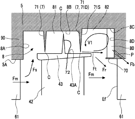
1. An axial flow turbine comprising:
a rotor extending along an axis;
a plurality of rotating blades each having a rotating blade body extending from the rotor outward in a radial direction and a shroud provided at an outside end portion of the rotating blade body in the radial direction, and arranged at intervals in a circumferential direction;
a casing surrounding the rotating blades from an outer side in the radial direction and having a recessed portion formed on an inner peripheral surface to accommodate the shrouds;
a fin protruding from a facing surface of the recessed portion of the casing, which faces the shroud, inward in the radial direction, wherein a clearance is formed between the fin and an outer peripheral surface of the shroud;
a stator blade support portion disposed close to a downstream end of the rotor with respect to the recessed portion on the inner peripheral surface of the casing;
a plurality of stator blades each extending from the stator blade support portion inward in the radial direction and arranged at intervals in the circumferential direction; and
an annular partition plate extending from a recessed portion downstream surface of the recessed portion, which is a surface on close to the downstream end of the rotor, toward an upstream end of the rotor and centered on the axis,
wherein a bypass flow path, is formed in the casing, wherein the bypass flow path has a first end formed in the recessed portion downstream surface and a second end formed in the inner peripheral surface of the casing.
|