| CPC E21B 4/16 (2013.01) | 16 Claims |

|
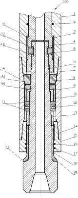
1. A drilling speed-enhancing device, comprising:
an outer cylinder;
a rotary main shaft arranged in an inner chamber of the outer cylinder and configured to rotate around its own axis;
an output main shaft arranged below the rotary main shaft and configured to be driven by the rotary main shaft to rotate around its own axis, a lower end of the output main shaft extending out of the inner chamber of the outer cylinder;
a percussion generator arranged between the output main shaft and the outer cylinder, and configured to drive the outer cylinder and the rotary main shaft to move upward relative to the output main shaft, so that under action of WOB, the rotary main shaft and the outer cylinder move downward to generate impact on the output main shaft,
the percussion generator comprising:
an upper cam arranged around an outer wall of the output main shaft in a clearance fit, and fixed relative to the outer cylinder in an axial direction and a circumferential direction, a lower end of the upper cam being provided with driven teeth; and
a lower cam arranged around the outer wall of the output main shaft, and provided at an upper end thereof with driving teeth, which form with the driven teeth a conjugate set of cam teeth,
wherein during rotation of the output main shaft the lower cam is driven to rotate, and the driving teeth act on the driven teeth to enable that the upper cam moves reciprocally in the axial direction and acts on the outer cylinder, and
wherein a lower cam seat is fixedly arranged around the output main shaft, and an outer wall of the lower cam seat is provided with engaging teeth protruding therefrom, each clamping tooth extending radially outward in a respective one of engaging slots formed on a wall of the lower cam, an upper end face of the lower cam seat abutting against a first step surface formed in an inner chamber of the lower cam.
|