| CPC E04G 21/123 (2013.01) [B21F 7/00 (2013.01); B25B 25/00 (2013.01)] | 3 Claims |

|
1. A binding machine comprising:
a wire feeder including a pair of rotatable members that rotate while holding a wire therebetween to feed the wire, the wire being wound around an object to be bound;
a binding part including a clamp and a rotating shaft, the clamp locking the wire wound around the object to be bound, and the rotating shaft rotating the clamp locking the wire;
a curl guide arranged along a looped path of the wire fed by the wire feeder; and
a draw-in guide configured to guide the wire curled by the curl guide to the binding part,
wherein the draw-in guide includes
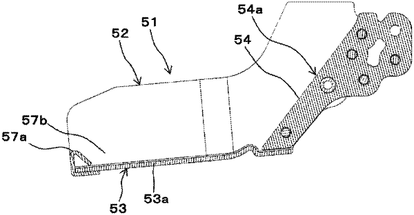
a first guide being a pair of side surface portions that restrict an axial position of a loop formed by the wire curled by the curl guide,
a second guide that restricts a radial position of the loop formed by the wire, the second guide being a bottom surface portion that connects the pair of side surface portions,
a guiding facilitation part that comes into contact with the wire from a radially outer side of the loop that is formed by the wire curled by the curl guide, and applies, to the wire, a force that changes a feeding path of the wire, the guiding facilitation part being located on the bottom surface portion, and
a guiding concave portion, provided on a downstream side of the guiding facilitation part in a feeding direction of the wire, into which the wire, expanding toward the radially outer side of the loop, enters, and
wherein the guiding facilitation part includes a convex portion provided on an open end of the draw-in guide and protruding from the bottom surface portion in a direction toward the curl guide, the open end being opened in a space surrounded by the pair of side surface portions and the bottom surface portion and being configured to allow the wire to enter therethrough.
|