| CPC D06F 39/022 (2013.01) [D06F 23/06 (2013.01); D06F 33/37 (2020.02); D06F 33/57 (2020.02); D06F 2105/42 (2020.02)] | 4 Claims |

|
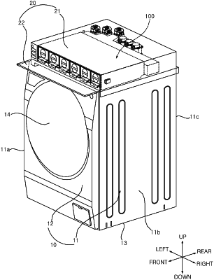
1. A washing machine comprising:
a tub configured to receive water;
a drum rotatably provided in the tub and configured to receive laundry; and
a detergent mixing device configured to mix additives supplied into the tub and including:
a pair of additive cartridges configured to receive a liquid additive; and
a peristaltic pump configured to selectively supply the additive discharged from the pair of additive cartridges to the tub, and
wherein the peristaltic pump includes:
a flow path switching motor configured to provide a rotational force;
a first tube configured to guide the additive discharged from a first cartridge of the pair of additive cartridges;
a second tube configured to guide the additive discharged from a second cartridge of the pair of additive cartridges;
a first rotor configured to be rotated by the flow path switching motor and configured to press the first tube;
a second rotor configured to be rotated by the flow path switching motor and configured to press the second tube;
a first rotary bearing supported by the first rotor, permitting a rotation of the first rotor in a first direction, and restricting a rotation of the first rotor in a second direction; and
a second rotary bearing supported by the second rotor, permitting a rotation of the second rotor in the second direction, and restricting a rotation of the second rotor in the first direction,
wherein the first rotor includes a first roller configured to, based on the first rotor being rotated, press the first tube, and the second rotor includes a second roller configured to, based on the second rotor being rotated, press the second tube,
wherein each of the first rotor and the second rotor includes:
a hollow central portion,
an upper plate portion extending radially outward from upper ends of the central portion, and
a lower plate portion extending radially outward from lower ends of the central portion, and
wherein the first and second rollers are disposed between the upper plate portion and the lower plate portion of the first and second rotors, respectively, and the first and second tubes are disposed between the upper plate portion and the lower plate portion of the first and second rotors, respectively.
|