| CPC B66B 5/18 (2013.01) [F16D 59/00 (2013.01); F16D 65/18 (2013.01); H02P 15/00 (2013.01); F16D 2121/22 (2013.01); H02K 33/02 (2013.01)] | 15 Claims |

|
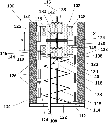
1. A frictionless safety brake actuator (100; 200) for use in an elevator system (50), comprising:
at least two stators, including a first stator (104) and a second stator (106) extending in respective substantially parallel planes;
a magnet array (102) positioned between the first and second stators (104, 106);
a linkage (108) that is actuatable so as to move a safety brake (58; 186) into frictional engagement with an elevator guide rail (56; 188), wherein the linkage (108) is attached to the magnet array (102), and wherein the magnet array (102) is moveable along an axis (115) extending substantially parallel to the first and second stators (104, 106) between a first position in which the linkage (108) is actuated and a second position in which the linkage (108) is not actuated; and
a biasing arrangement (118) arranged to apply a biasing force to the magnet array (102) to bias the magnet array (102) towards the first position;
wherein the magnet array (102) comprises a first magnet set and a second magnet set, wherein the first and second magnet sets comprise at least one magnet each and at least three magnets in total, wherein the magnet(s) (130, 132) of the first magnet set is/are arranged alternately with the magnet(s) (134) of the second magnet set in a stack, wherein the or each magnet in the first magnet set is an electromagnet (130, 132), and wherein the magnet array (102) produces a magnetic field (158, 168);
wherein the electromagnet(s) (130, 132) in the first magnet set and the magnet(s) (134) in the second magnet set each have a respective orientation (154, 156, 134, 164, 166) such that when a forward current (152) is supplied to the electromagnet(s) (130, 132) in the first magnet set, the magnetic field (158) is stronger on a first side of the magnet array (102) adjacent to the first stator (104) than on a second, opposing side of the magnet array (102) adjacent to the second stator (106), and when a reverse current (162) is supplied to the electromagnet(s) (130, 132) in the first magnet set, the magnetic field (168) is stronger on the second side of the magnet array (102) than on the first side of the magnet array (102);
wherein the first and second stators (104, 106) each comprise a respective array of discrete magnetic elements (126, 128) that extends parallel to the axis (115), wherein the discrete magnetic elements (126, 128) have a staggered configuration in which the discrete magnetic elements (126, 128) on the first stator (104) are displaced in the direction of the axis (115) relative to the discrete magnetic elements (126, 128) on the second stator (106).
|