| CPC B32B 37/0046 (2013.01) [B32B 37/10 (2013.01); B32B 37/003 (2013.01); B32B 38/1866 (2013.01); B32B 2383/00 (2013.01); B32B 2457/206 (2013.01); G09F 9/301 (2013.01)] | 17 Claims |

|
1. A lamination device, configured to laminate a cover plate onto a flexible display panel, comprising:
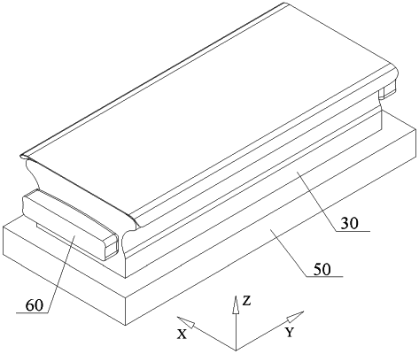
an elastic lamination seat, comprising a deformation bearing portion, the deformation bearing portion comprising a bearing surface for bearing a to-be-laminated flexible display panel, and the bearing surface being configured as a curved surface protruding toward the cover plate;
an auxiliary bearing film configured to pre-bend and fix the to-be-laminated flexible display panel on the bearing surface when the elastic lamination seat is in a natural state; and,
a driving mechanism connected to the elastic lamination seat and configured to drive the elastic lamination seat to move toward or away from the cover plate, wherein when the driving mechanism drives the elastic lamination seat to move toward the cover plate, the elastic lamination seat is squeezed to produce elastic deformation and the bearing surface gradually laminates the flexible display panel onto the cover plate from a middle to two sides; wherein
the bearing surface comprises second cambered surfaces at two ends, a first cambered surface between the two second cambered surfaces, and a third cambered surface;
the third cambered surface is tangentially connected with ends of the second cambered surfaces away from the first cambered surface, the third cambered surface is recessed toward the elastic lamination seat; the flexible display panel after being laminated onto the cover plate comprises curved sections at two ends and a flat section between the two curved sections;
when the driving mechanism applies an acting force to the elastic lamination seat, deformation of the third cambered surface applies an acting force to the second cambered surface along a tangential direction of a junction of the third cambered surface and the second cambered surface so as to promote the second cambered surface to be filled to the curved section of the flexible display panel and laminate the curved section with a cambered section of the cover plate;
wherein the elastic lamination seat further comprises a deformation supporting portion, the deformation supporting portion comprises a supporting surface opposite to the bearing surface and flat side surfaces located at two ends of the supporting surface, the supporting surface and each of the flat side surfaces are connected by a transitional surface, and the transitional surface is configured as a stepped surface;
wherein a maximum distance between a circle center of the second cambered surface and the first cambered surface in a third direction is H2, a distance between an end of the curved section away from the flat section and the flat section in the third direction is H1, and H2 is less than or equal to H1, wherein the third direction is a direction parallel to a symmetry axis of a cross section of the elastic lamination seat;
wherein the lamination device comprises stop blocks located at two sides of the elastic lamination seat in a second direction, each of the stop blocks is movable, each of the stop blocks can move along the second direction and can move along the third direction, before the driving mechanism drives the elastic lamination seat to move towards the cover plate, each of the stop blocks moves to a position corresponding to a position of the third cambered surface.
|