| CPC B29C 45/7312 (2013.01) | 20 Claims |

|
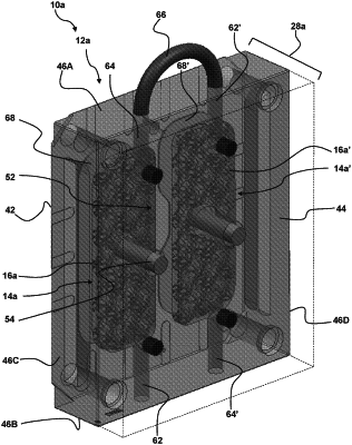
1. A fluid cooled mold plate comprising
a front side, a rear side, and a perimeter extending between the front side and the rear side;
a cooling chamber formed within the mold plate, the cooling chamber having a front wall, a rear wall, and a perimeter wall extending between the front wall and the rear wall;
an inlet fluid duct extending from a first side of the perimeter of the mold plate to a first end of the cooling chamber;
an outlet fluid duct extending from a second side of the perimeter of the mold plate to a second end of the cooling chamber that is opposite to the first end of the cooling chamber; and
the cooling chamber being occupied by a dispersion mesh secured between the front wall and the rear wall of the cooling chamber,
wherein the mold plate includes a front plate portion and a rear plate portion, the front plate portion and the rear plate portion being secured together to define the cooling chamber therebetween,
wherein the front plate portion includes a first thickness portion and a second thickness portion thicker than the first thickness portion, and a conductive insert extending into the second thickness portion from the cooling chamber.
|