| CPC B25H 1/0007 (2013.01) [B25H 1/00 (2013.01); B25H 1/16 (2013.01); B65D 19/44 (2013.01)] | 16 Claims |

|
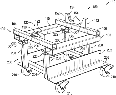
1. An engine stand, comprising:
a cradle assembly configured to support an engine assembly, comprising:
an upper frame assembly comprising:
a first lateral frame member and a second lateral frame member;
a first longitudinal frame member and a second longitudinal frame member extending from the first lateral frame member to the second lateral frame member and fixedly and unmovably coupled to the first lateral frame member and the second lateral frame member;
a cylindrical pin coupled to the first lateral frame member so that the cylindrical pin is offset from a top surface of the first lateral frame member in a direction toward the second lateral frame member, wherein the cylindrical pin is configured to be received by an aperture defined by the engine assembly; and
a rest coupled to the second lateral frame member, the rest having an engagement surface positioned to contact the engine assembly when the cradle assembly supports the engine assembly, wherein an entirety of the rest is positioned laterally inwardly from an outer lateral edge of both of the first longitudinal frame member and the second longitudinal frame member, and wherein a portion of the engagement surface is angled relative to a horizontal plane defined by the first lateral frame member and the second lateral frame member; and
a dolly coupled to the cradle assembly, comprising:
a lower frame assembly, the lower frame assembly comprising a set of horizontal frame members longitudinally offset from one another and extending between a pair of longitudinally extending frame members;
a pair of first receiving channels coupled to the lower frame assembly and positioned to receive the first lateral frame member, wherein the cylindrical pin is positioned between the first receiving channels when the first receiving channels receive the first lateral frame member;
a pair of second receiving channels coupled to the lower frame assembly and positioned to receive the second lateral frame member, and wherein the rest is positioned between the second receiving channels when the second receiving channels receive the second lateral frame member; and
a plurality of wheels rotatably coupled to the lower frame assembly and configured to support the lower frame assembly;
wherein the set of horizontal frame members are fixedly coupled to a pair of vertically extending frame members, and wherein the first lateral frame member includes a coextensive portion that is at least partially coextensively provided above the first longitudinal frame member, and the second lateral frame member includes a coextensive portion that is at least partially coextensively provided above the second longitudinal frame member, wherein the coextensive portions of the first lateral frame member and the second lateral frame member are parallel to one another.
|