| CPC B25F 5/001 (2013.01) [B24B 23/04 (2013.01); B25F 1/02 (2013.01); B25F 3/00 (2013.01); B25F 5/02 (2013.01); B26B 7/00 (2013.01)] | 19 Claims |

|
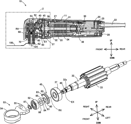
1. A power tool configured to process a workpiece by driving a tool accessory in an oscillating manner, the power tool comprising:
a motor having a rotary shaft that is rotationally driven in one direction;
an eccentric shaft that extends from one end of the rotary shaft and is configured to be rotated around a rotation center axis of the rotary shaft, at a position that is eccentric from the rotation center axis of the rotary shaft in a radial direction orthogonal to the rotation center axis, by rotation of the rotary shaft;
a motion converting mechanism that is configured to connect the tool accessory and the eccentric shaft and convert one revolution of the eccentric shaft to one reciprocating oscillation of the tool accessory; and
a balancer that is mounted onto an outer periphery of the rotary shaft and configured to rotate together with the rotary shaft,
wherein:
when viewed along the rotation center axis, (1) a first imaginary line passes the rotation center axis and an eccentric axis, which is a center axis of the eccentric shaft, (2) an imaginary perpendicular line crosses perpendicularly to the first imaginary line and passes through the rotation center axis, (3) a center of gravity of the balancer is located in a region on a side opposite to the eccentric axis across the imaginary perpendicular line, (4) a second imaginary line passes the rotation center axis and the center of gravity of the balancer, and (5) the second imaginary line is inclined at an inclination angle larger than 0° and smaller than 90° in a direction opposite to a rotating direction of the rotary shaft relative to the first imaginary line.
|