| CPC A61F 2/4465 (2013.01) [A61B 90/39 (2016.02); A61F 2/4611 (2013.01); A61F 2/30734 (2013.01); A61F 2002/3008 (2013.01); A61F 2002/3082 (2013.01); A61F 2002/30131 (2013.01); A61F 2002/30364 (2013.01); A61F 2002/30365 (2013.01); A61F 2002/30538 (2013.01); A61F 2002/30593 (2013.01); A61F 2002/30594 (2013.01); A61F 2002/30616 (2013.01); A61F 2002/30622 (2013.01); A61F 2002/30785 (2013.01); A61F 2002/30843 (2013.01); A61F 2002/30904 (2013.01); A61F 2002/4627 (2013.01); A61F 2002/4629 (2013.01); A61F 2220/0033 (2013.01); A61F 2230/0013 (2013.01); A61F 2250/0006 (2013.01); A61F 2250/0098 (2013.01)] | 19 Claims |

|
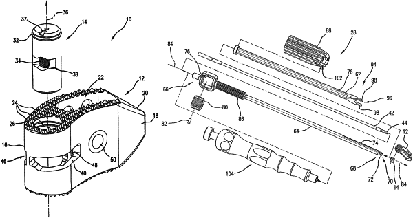
1. An assembly for implant installation between adjacent vertebral bodies of a patient, comprising:
an implant having a support body and a rotatable insert therein;
the support body having a proximal end portion and a distal end portion and the support body being configured and dimensioned for installation between adjacent vertebral bodies;
wherein the support body includes a superior surface and an inferior surface,
wherein the support body defines a longitudinal opening extending between the superior surface and the inferior surface, and positioned between the proximal end and the distal portion to accommodate the rotatable insert therein, and
wherein the insert is rotatable about a central longitudinal axis within the longitudinal opening to permit the support body to rotate about the insert and the central longitudinal axis; and
wherein the insert includes a threaded hole extending transverse to the longitudinal axis to interface with an installation instrument and a counter-torque slot adjacent the threaded hole and extending transversely to the threaded hole.
|