| CPC A61B 17/0686 (2013.01) [A61B 17/072 (2013.01); A61B 17/07207 (2013.01); B33Y 80/00 (2014.12); A61B 2017/00389 (2013.01); A61B 2017/00526 (2013.01); A61B 2017/07257 (2013.01); A61B 2017/07271 (2013.01); A61B 2017/07278 (2013.01); A61B 2017/07285 (2013.01)] | 28 Claims |

|
1. A method of stapling, comprising:
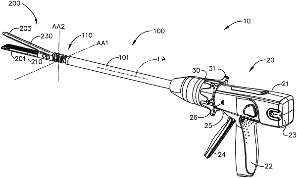
articulating a surgical stapling assembly, wherein the surgical stapling assembly comprises a first jaw, a second jaw, an articulation joint comprising a fixed pivot axis, a closure drive comprising a first flexible rotary drive extending through the articulation joint, and a firing drive comprising a second flexible rotary drive extending through the articulation joint and rotatable independent of the first flexible rotary drive, wherein the surgical stapling assembly further comprises a 3D-printed component, and wherein the articulating step comprises articulating the surgical stapling assembly about the fixed pivot axis by way of the articulation joint;
activating, by a closure trigger, the closure drive, wherein the closure drive further comprises a closure screw and a closure wedge threadably coupled to the closure screw, wherein the closure wedge is configured to engage the first jaw to move the first jaw from an open position to a closed position upon a rotation of the first flexible rotary drive; and
activating, by a firing trigger, the firing drive, wherein the firing drive further comprises a firing screw and a firing member threadably coupled to the firing screw, wherein the firing member comprises an upper flange and a lower flange configured to cammingly engage the first jaw and the second jaw and to advance a cutting member and a staple-firing sled during an application of a distal firing motion force to the firing member upon a rotation of the second flexible rotary drive.
|