|
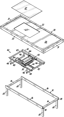
1. A bedding foundation comprising: a generally rectangular frame made of hollow members supported by legs; a rigid platform supported by the generally rectangular frame, the rigid platform having a footprint larger than the generally rectangular frame and extending outwardly from the perimeter of the generally rectangular frame, the rigid platform further having an opening; a cover secured to the rigid platform and covering the opening in the rigid platform; roller rails secured to the rigid platform, each of the roller rails being a unitary member having a horizontally oriented mounting flange, a connecting portion extending downwardly from the horizontally oriented mounting flange and an inverted V-shaped lower portion extending inwardly from a lower edge of the connecting portion; hollow uprights secured to the roller rails and extending downwardly from the roller rails; hollow cross members secured to the uprights and extending therebetween a motorized linear actuator comprising a threaded rod rotated by a motor and a bus movable upon rotation of the threaded rod, the threaded rod extending between the cross members for moving the bus; a roller tray bracket secured to the bus; a roller carriage secured to the roller tray bracket and being moveable by the linear actuator, said roller carriage including a roller tray; a lifter inside the roller tray for lifting a lifter plate; two L-shaped roller mounting brackets directly secured to an upper surface of the lifter plate, one L-shaped roller mounting bracket being on each side of the lifter plate; a single roller extending between the roller mounting brackets; and four wheels, two per side for engaging the roller rails and guiding movement of the roller carriage, wherein said roller of the roller carriage is movable in a horizontal direction by the linear actuator and movable in a vertical direction by the lifter.
|