| CPC A45D 20/122 (2013.01) | 7 Claims |

|
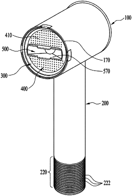
1. A hair dryer, comprising:
a main body comprising a discharge unit configured to discharge fluid outside of the main body; and
a handle provided at one side of the main body, wherein the discharge unit comprises a plurality of discharge areas configured to discharge fluid, wherein the discharge unit is configured to selectively discharge fluid through one of plurality of the discharge areas, wherein the plurality of the discharge areas comprises:
an outer area arranged at a front surface of the main body and formed in a ring shape extending along a circumferential direction of the main body; and
an inner area provided at the front surface of the main body and arranged within the outer area, wherein the discharge unit comprises:
a discharge base inserted into the main body and having a front surface that forms the front surface of the main body, wherein the outer area is configured to surround the front surface of the discharge base along the circumferential direction, and wherein the inner area is arranged on the front surface of the discharge base, wherein the discharge unit is configured to discharge fluid through one of the inner area or the outer area selected based on a displacement of the discharge base, wherein the inner area comprises:
a first inner area arranged at a center of the front surface provided in the main body; and
a second inner area arranged between the first inner area and the outer area and surrounding the first inner area and provided at the front surface and surrounding the first inner area along the circumferential direction, and wherein the discharge unit is configured to discharge fluid through one area selected from the outer area, the first inner area, and the second inner area, and wherein the discharge unit is configured to discharge fluid through one area selected from the first inner area or the second inner area in a state in which the inner area is selected by rotation of the discharge base.
|