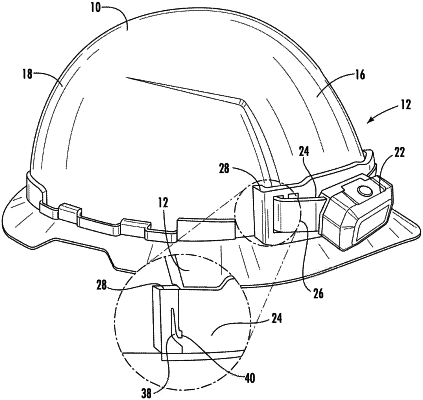
| CPC A42B 3/044 (2013.01) [A42B 3/042 (2013.01); A42B 3/0406 (2013.01); A42B 3/0426 (2013.01); A42B 3/0446 (2013.01)] | 21 Claims |

|
1. A hard hat system, comprising:
a hard hat comprising:
a brim extending radially outward from a bottom portion of an exterior surface of the hard hat and
a raised mounting ridge extending outward from the exterior surface of the hard hat and positioned above the brim, the raised mounting ridge comprising opposing edges; and
a mounting bracket that removably mounts to the raised mounting ridge of the hard hat, the mounting bracket comprising:
a first end having a first side surface;
a second end opposing the first end and having a second side surface;
a top surface extending between the first end and the second end;
a bottom surface opposing the top surface and extending between the first end and the second end;
a first slot located at the first end, the first slot configured to receive one of the opposing edges of the raised mounting ridge; and
a second slot located at the second end, the second slot configured to receive the other of the opposing edges of the raised mounting ridge;
wherein a length of the mounting bracket is defined between the first side surface and the second side surface, and wherein a height of the mounting bracket is defined between the top surface and the bottom surface.
|