| CPC H05K 7/186 (2013.01) [G02B 6/4446 (2013.01); G02B 6/44465 (2023.05)] | 20 Claims |

|
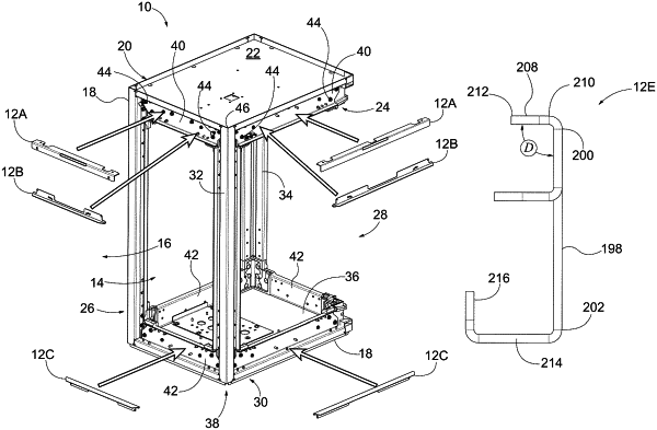
1. A deflector configured to reduce entry of at least one of dust or fluid into an enclosure configured to enclose in an interior thereof a plurality of optical communication connections, the deflector defining a longitudinal axis extending between a first end of the deflector and a second end of the deflector opposite the first end, the deflector comprising:
an elongated first leg defining a first intersection edge and a first remote edge opposite the first intersection edge, the first leg defining a first hole adjacent the first end of the deflector and a second hole adjacent the second end of the deflector; and
an elongated second leg defining a second intersection edge and a second remote edge opposite the second intersection edge,
wherein the first intersection edge and the second intersection edge are coupled to one another to define a deflector angle, and
wherein the first hole is configured to receive a first mounting stud associated with the enclosure, and the second hole is configured to receive a second mounting stud associated with the enclosure;
wherein the first leg is coupled to an outward facing side of a horizontal frame member of the enclosure, such that the second leg extends in a direction away from a plane defined by the outward facing side of the horizontal frame member; and
wherein the deflector angle is substantially perpendicular, and the deflector further comprises:
a first flange extending from the first remote edge of the first leg in a direction substantially parallel to the second leg; and
a second flange extending from a remote edge of the first flange in a direction substantially parallel to the first leg.
|