| CPC B28B 1/001 (2013.01) [B29C 64/165 (2017.08); B29C 64/205 (2017.08); B29C 64/218 (2017.08); B29C 64/329 (2017.08); B29C 64/343 (2017.08); B33Y 10/00 (2014.12); B33Y 30/00 (2014.12); B65G 47/44 (2013.01); B65G 47/78 (2013.01)] | 11 Claims |

|
1. A powder spreading apparatus, comprising:
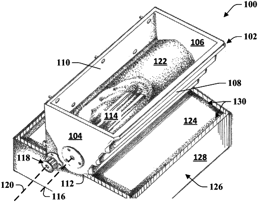
a hopper having a first end, a second end opposite from the first end, a front wall, a rear wall opposite from the front wall, and a floor, wherein the front wall, the rear wall, the first end, the second end, and the floor define an interior;
an impeller disposed within the interior of the hopper, wherein the impeller comprises a plurality of circumferentially spaced flutes and is configured to rotate about an impeller axis that extends from the first end of the hopper to the second end of the hopper;
a spreader rod coupled to the hopper and extending along a spreader rod axis parallel to the impeller axis, wherein the spreader rod is configured to rotate about the spreader rod axis;
a gantry, wherein the hopper is coupled to the gantry;
a gantry motor configured to move the gantry;
an impeller motor configured to rotate the impeller;
a spreader rod motor configured to rotate the spreader rod;
a controller configured to independently control each of the gantry motor, the impeller motor, and the spreader rod motor, wherein the controller is configured to operate the impeller motor to start depositing powder in a print area as the gantry moves the hopper across the print area, operate the spreader rod motor to start the spreader rod and smooth out the powder, and upon the gantry reaching a predetermined position, stop operation of the impeller motor to stop depositing the powder while continuing to operate the spreader rod motor;
a build box having interior surfaces that enclose the print area; and
a buffer zone around the print area that is between the print area and the interior surfaces of the build box,
wherein the predetermined position corresponds to a beginning of the buffer zone, the interior surfaces of the build box define an outer boundary of the buffer zone, and the predetermined position stops operation of the impeller motor to deposit substantially all of the powder within the build box, wherein the width of the buffer zone is predetermined based on flow properties of the powder within the hopper.
|