| CPC H04B 10/50575 (2013.01) [G02F 1/0123 (2013.01); G02F 1/212 (2021.01)] | 14 Claims |

|
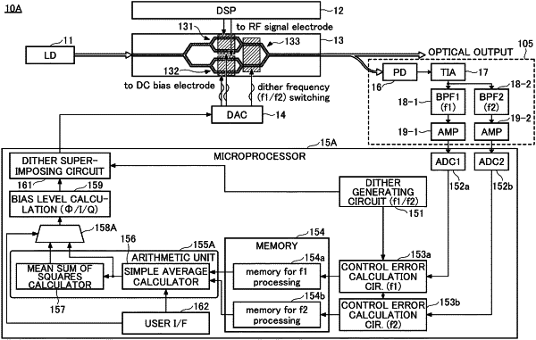
1. An optical transmitter comprising:
an electro-optic modulator;
a monitor circuit that monitors output light of the electro-optic modulator; and
a processor that controls a bias voltage of the electro-optic modulator using a monitoring result of the monitor circuit,
wherein the processor superimposes a first dither signal with a first frequency and a second dither signal with a second frequency different from the first frequency, onto one bias voltage in a time sharing manner, calculates a first control error based on a first component oscillating at the first frequency and a second control error based on a second component oscillating at the second frequency based on the monitoring result, and determines a control value for controlling the bias voltage using the first control error and the second control error,
wherein the electro-optic modulator is a Mach-Zehnder modulator in which a first child modulator and a second child modulator are nested to form a parent modulator, and
wherein the processor superimposes the first dither signal onto each of a first bias for the first child modulator, a second bias for the second child modulator, and a third bias for the parent modulator in a first section of a bias control cycle to detect the first component from the output light of the electro-optic modulator, and superimposes the second dither signal onto each of the first bias, the second bias, and the third bias in a second section of the bias control cycle to detect the second component from the output light of the electro-optic modulator.
|