| CPC H03K 17/08 (2013.01) [H02H 1/0007 (2013.01); H03K 5/24 (2013.01); G05F 1/562 (2013.01); G05F 1/573 (2013.01); H03K 2005/00013 (2013.01)] | 21 Claims |

|
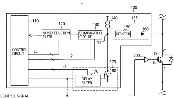
1. Electronic circuitry comprising:
a detection circuit including a diode, a cathode side of the diode being connected to one end of a semiconductor switching element and an anode side of the diode being connected to a first node;
a comparator circuit configured to compare a voltage of the first node and a threshold voltage and generate a first signal;
a first filter connected between the first node and another end of the semiconductor switching element and configured to suppress the voltage of the first node in a first period based on a control signal indicating turn-on of the semiconductor switching element; and
a control circuit configured to determine at least one of the threshold voltage and the first period based on the first signal.
|