US 11,888,465 B2
Bandpass filter with frequency separation between shunt and series resonators set by dielectric layer thickness
Viktor Plesski, Gorgier (CH); Soumya Yandrapalli, Lausanne (CH); Robert B. Hammond, Santa Barbara, CA (US); Bryant Garcia, Belmont, CA (US); Patrick Turner, San Bruno, CA (US); Jesson John, Dublin, CA (US); and Ventsislav Yantchev, Sofia (BG)
Assigned to Murata Manufacturing Co., Ltd., Nagaokakyo (JP)
Filed by Murata Manufacturing Co., Ltd., Nagaokakyo (JP)
Filed on Aug. 20, 2021, as Appl. No. 17/408,095.
Application 17/408,095 is a continuation of application No. 17/109,812, filed on Dec. 2, 2020.
Application 17/109,812 is a continuation in part of application No. 16/689,707, filed on Nov. 20, 2019, granted, now 10,917,070, issued on Feb. 9, 2021.
Application 16/689,707 is a continuation of application No. 16/230,443, filed on Dec. 21, 2018, granted, now 10,491,192, issued on Nov. 26, 2019.
Claims priority of provisional application 62/753,815, filed on Oct. 31, 2018.
Claims priority of provisional application 62/748,883, filed on Oct. 22, 2018.
Claims priority of provisional application 62/741,702, filed on Oct. 5, 2018.
Claims priority of provisional application 62/701,363, filed on Jul. 20, 2018.
Claims priority of provisional application 62/685,825, filed on Jun. 15, 2018.
Prior Publication US 2021/0384889 A1, Dec. 9, 2021
Int. Cl. H03H 9/56 (2006.01); H03H 9/02 (2006.01); H03H 9/13 (2006.01); H03H 9/17 (2006.01); H03H 3/02 (2006.01); H10N 30/87 (2023.01)
CPC H03H 9/568 (2013.01) [H03H 3/02 (2013.01); H03H 9/02015 (2013.01); H03H 9/02031 (2013.01); H03H 9/02062 (2013.01); H03H 9/02228 (2013.01); H03H 9/132 (2013.01); H03H 9/174 (2013.01); H03H 9/176 (2013.01); H03H 9/562 (2013.01); H03H 9/564 (2013.01); H03H 9/02039 (2013.01); H03H 2003/023 (2013.01); H10N 30/877 (2023.02)] 20 Claims
OG exemplary drawing
 
1. A filter device, comprising:
a substrate;
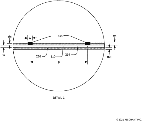
a piezoelectric plate having front and back surfaces, the back surface on a surface of a substrate, portions of the piezoelectric plate forming one or more diaphragms, each diaphragm spanning a respective cavity in the substrate;
a conductor pattern on the front surface, the conductor pattern including a plurality of interdigital transducers (IDTs) of a respective plurality of acoustic resonators including a shunt resonator and a series resonator, interleaved fingers of each of the plurality of IDTs on a diaphragm of the one or more diaphragms;
a first dielectric layer having a first thickness on the front surface between the fingers of the IDT of the shunt resonator; and
a second dielectric layer having a second thickness on the front surface between the fingers of the IDT of the series resonator, wherein
the piezoelectric plate and all of the plurality of IDTs are configured such that radio frequency signals applied to the plurality of IDTs excite respective primary shear acoustic modes within the one or more diaphragms, and
the first thickness is greater than the second thickness.