| CPC H03F 1/34 (2013.01) [H03F 3/45475 (2013.01); H03F 2200/171 (2013.01); H03F 2200/331 (2013.01)] | 17 Claims |

|
1. An amplifier comprising:
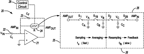
an amplifier circuit having an inverting input, a non-inverting input, and a negative feedback path between an output of the amplifier circuit and the inverting input of the amplifier circuit;
a feedback capacitor forms part of the negative feedback path;
a feedback resistor in parallel with the feedback capacitor forms part of the negative feedback path, wherein the feedback resistor is comprised of a low pass filter in series with a switched capacitor resistor, such that the low pass filter is electrically coupled to the output of the amplifier circuit and the switched capacitor resistor is electrically coupled to the inverting input of the amplifier circuit, wherein high pass corner of the switched capacitor resistor is lower than corner of the low pass filter; and
a control circuit configured to supply a drive signal for controlling the switched capacitor resistor, where switching frequency of the drive signal is less than lower bound of bandwidth of an input signal to the amplifier circuit.
|