| CPC H02M 7/003 (2013.01) [B60L 15/007 (2013.01); B60L 50/51 (2019.02); H02M 7/797 (2013.01)] | 5 Claims |
|
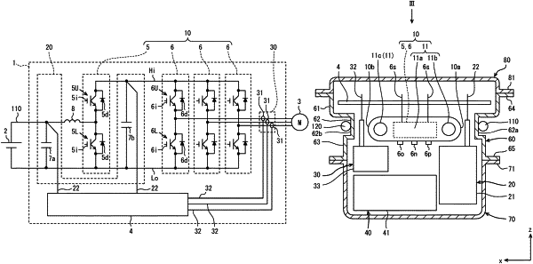
1. A power conversion device that converts electric power supplied to a vehicle-mounted motor by an upper and lower arm circuit, the power conversion device comprising:
a semiconductor unit having a semiconductor module in which switching elements of upper and lower arm circuits are resin-sealed, and a cooler configured to cool the semiconductor module;
a terminal unit having an output terminal of the semiconductor module, a relay output terminal configured to electrically connect windings of the vehicle-mounted motor, and a terminal block configured to hold the relay output terminal;
a capacitor unit having a smoothing capacitor connected in parallel to the upper and lower arm circuits to smooth a voltage pulsation, and a capacitor case accommodating the smoothing capacitor;
a control board configured to control an operation of the switching elements; and
a case in which the control board, the semiconductor unit, the terminal unit, and the capacitor unit are housed,
wherein
the semiconductor unit is arranged at a position facing a plate surface of the control board,
the terminal unit and the capacitor unit are arranged side by side in a direction along the plate surface on an opposite side of the control board with respect to the semiconductor unit,
a direction perpendicular to the plate surface of the control board is referred to as a z direction, a direction in which the terminal unit and the capacitor unit are arranged side by side is referred to as a x direction, and a direction perpendicular to the z direction and the x direction is referred to as a y direction,
of both ends of the semiconductor unit in the x direction, one end is referred to as a first end and the other end is referred to as a second end,
at least a part of the capacitor unit or the terminal unit is located outside the first end in the x direction, and
a recess in which an electrical wiring is arranged is formed in a portion of the case facing the first end so as to be recessed inside the case.
|