| CPC H01R 13/639 (2013.01) [H01R 4/18 (2013.01); H01R 12/55 (2013.01); H01R 13/6272 (2013.01); H01R 13/64 (2013.01)] | 9 Claims |

|
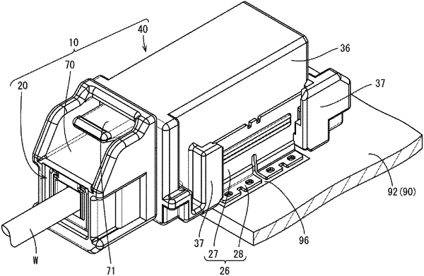
1. A connector comprising:
a circuit board housing fixed to a circuit board;
circuit board terminals held by the circuit board housing;
an electric cable housing coupled to an end of an electric cable;
electric wire terminals held by the electric cable housing; and
a holder maintaining electrical connection between the circuit board terminals and the electric wire terminals, the holder being fixed to the circuit board housing and the electric cable housing, and the holder having a strength less than a strength of the circuit board housing and a strength of the electric cable housing, wherein
the electric cable includes two covered electric wires and a sheath that collectively covers the covered electric wires,
the covered electric wires are side by side and coupled to the electric wire terminals, respectively,
a crimping member made of metal is crimped on the sheath,
the crimping member includes two projections that project in an arrangement direction in which the covered electric wires are arranged,
the projections are fitted in locking recesses that are recesses of the electric cable housing, respectively, and
the projections abut inner walls of the locking recesses in the extending direction in which the electric cable extends.
|