| CPC G11B 5/3932 (2013.01) [G11B 5/3909 (2013.01); G11B 5/3912 (2013.01); G11B 5/3967 (2013.01); G11B 5/4826 (2013.01); G11B 5/4833 (2013.01); G11B 2005/0008 (2013.01); G11B 2005/0018 (2013.01)] | 7 Claims |

|
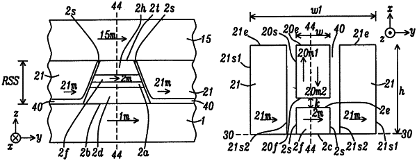
1. A magnetic read head structure, comprising:
(a) a tunneling magnetoresistive (TMR) sensor formed on a bottom shield and with a front side at an air bearing surface (ABS), and wherein the TMR sensor comprises a capping layer formed on a free layer (FL), and a reference layer (RL) separated from the FL with a tunnel barrier laver, and wherein the TMR sensor has a backside that extends from a top surface on the capping layer to a top surface of the bottom shield, and wherein the FL with has a first magnetization substantially in a first cross-track direction, and has two sidewalls formed equidistant from a center plane that bisects the TMR sensor;
(b) the bottom shield;
(c) a longitudinal (L) biasing layer that is adjacent to each of the two FL sidewalls, and each L biasing layer has a front side at the ABS, a second magnetization in the first cross-track direction, and provides a bias field to stabilize the first magnetization in the free layer (FL);
(d) a permanent magnet (PM) layer with a front side that faces a backside of the FL and is a greater distance from the ABS than the TMR sensor backside, a width that is substantially equal to a width of the FL, and separated from the FL by an insulation layer having a top surface that is coplanar with the capping layer top surface, and wherein the PM layer has a magnetization that is orthogonal to the ABS and initialized in a direction that adjusts a FL bias point so that the absolute value of TMR sensor asymmetry is reduced and is closer to 0% than in the absence of the initialized PM layer; and
(e) a top shield that contacts a top surface of the TMR sensor.
|