| CPC G06F 17/11 (2013.01) [E21B 21/08 (2013.01); E21B 47/18 (2013.01)] | 2 Claims |

|
1. An oscillating shear valve of a continuous pulse generator, comprising:
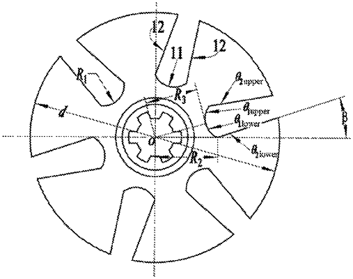
a rotator and a stator which are coaxially mounted, wherein the stator and the rotator have a same number nb of vanes and valve orifices with same structures between the vans, wherein nb=4, 6, 8; each of the valve orifices comprises a circular arc line, two straight line segments and two fillets, each fillet is tangent to the circular arc line and one of the straight line segments, an angle of each valve orifice of the vans is π/nb, and a structure of each valve orifice is designed according to following method:
establishing a characteristic equation of rotation angular displacement of the rotator according to an angular speed of the rotator during constant-speed rotating, wherein the characteristic equation is expressed as:
ϕ=ωut (1)
wherein ϕ is the rotation angular displacement of the rotator, that is, a rotation angle; ωu is the angular speed of the rotator during constant-speed rotating, with a unit: rad/s; and t is constant-speed rotation time;
setting the circular arc line within a first quadrant, dividing the circular arc line into an upper circular arc θ1upper(r) and a lower circular arc θ1lower(r) by taking a midpoint of the circular arc line as a boundary, and respectively establishing polar coordinate equations of the upper circular arc θ1upper(r) and the lower circular arc θ1lower(r) as:
 wherein r is a polar radius of any point on the circular arc line, and R1 is a radius of the circular arc line; R2 is a maximum polar radius of the circular arc line and is equal to a length of a connecting line segment between a polar point and an upper end point or a lower end point of the circular arc line; R3 is a minimum polar radius of the circular arc line and is equal to a length of a connecting line segment between the polar point and the midpoint of the circular arc line; L1 is a polar radius of a center of a circle of the circular arc line;
 is a polar angle corresponding to R3; and nb is the number of the vanes;
respectively establishing polar coordinate equations of an upper straight line segment θ2upper(r) and a lower straight line segment θ2lower(r) as:
 wherein β is a bending angle formed by the upper straight line segment θ2upper(r) and the upper circular arc θ1upper(r) or the lower straight line segment θ2lower(r) and the lower circular arc θ1lower(r);
establishing a polar coordinate equation of the two fillets as:
(x−x0)2+(y−y0)2=R02 (22)
wherein (x,y) are coordinates of any point on circles where the fillets are located, and (x0, y0) are circle center coordinates of the circles where the fillets are located; and R0 is a radius of each of the fillets;
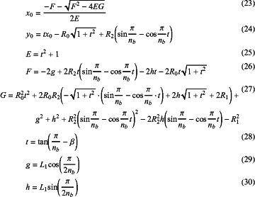
establishing relational expressions among a plurality of variables x0, y0, L1, R0, R1, R2, R3, β as:
 wherein E, F, G, t, g and h are all intermediate variables;
calculating a mud throttling area A(ϕ) formed when the oscillating shear valve rotates:
 wherein A1 is an annular area formed by taking the maximum polar radius R2 as an internal radius and a radius d/2 of the rotator as an external radius and a differential angle between the angle of each of the valve orifices π/nb of the vans and the rotation angle ϕ as a central angle; A2 is an area defined by the circular arc lines and a circle formed by taking the polar point O as a center and R2 as a radius; A3 is an area defined by an extension line of R2 a circumferential line of the rotator and one of the straight line segments; A4 is an area defined by the circle formed by taking the polar point O as the center and R2 as the radius and the two straight line segments; A5 is an area defined by the circular arc line, one fillet and one straight line segment and is segmented into four parts A51, A52, A53 and A54 to be calculated; A6 is an area defined by the two fillets and the two straight line segments; A7 is an area defined by the two fillets; Amin is a minimum flow area of the oscillating shear valve; θ1 is a rotation angle when the oscillating shear valve rotates to a position where an end point of one straight line segment of the rotator coincides with an end point of one straight line segment of the stator; θ2 is a rotation angle when the oscillating shear valve rotates to a position where one fillet of the rotator is tangent to one fillet of the stator; (l,u) are coordinates of a tangent point of one fillet and the circular arc line; (v,c) are coordinates of a tangent point of one straight line segment and one fillet; (j,z) and (o,k) are coordinates of intersection points of a straight line taking a tangent value of the rotation angle as a slope and passing through the polar point O and a circle where one fillet is located; (a,b) are coordinates of an intersection point of a straight line where one straight line segment is located and a straight line passing through (j,z) and the polar point O; rj(ϕ) and rmax(ϕ) are both intermediate variables; and D is an external diameter of the stator; and
according to a relation between a thin-walled cutting edge fluid differential pressure ΔP(ϕ) and the mud throttling area A(ϕ), establishing a relational expression between the mud throttling area and the fluid differential pressure as:
 wherein ρ is a density of mud, with a unit: kg/m3; Q is a flow amount of a drilling fluid, with a unit: m3/s; and Cd is a flow coefficient which is 0.6-0.8;
determining the radius R1 and the maximum polar radius R2 of the circular arc line, the bending angle β and the radius R0 of each of the fillets by adopting a correlation coefficient index R of the fluid differential pressure ΔP(ϕ) and a standard sinusoidal wave to complete design of the valve orifices of the oscillating shear valve; wherein the correlation coefficient index R is expressed as:
 wherein ΔP0(ϕ) is a standard sinusoidal pressure wave signal, and T is a differential pressure signal period of the valve orifices of the oscillating shear valve.
|