| CPC G02B 27/0149 (2013.01) [G02B 27/0101 (2013.01); B60K 35/00 (2013.01); B60K 2370/1529 (2019.05); B60K 2370/23 (2019.05); B60K 2370/67 (2019.05); G02B 2027/0159 (2013.01)] | 4 Claims |
|
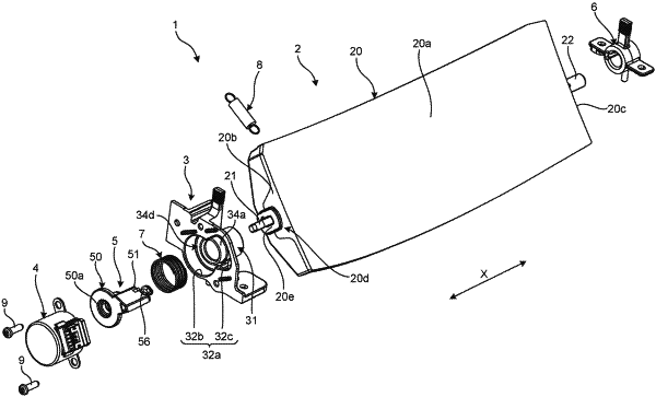
1. A head-up display device comprising:
an image display device configured to output display light of an image;
a rotatable mirror having a reflecting surface configured to reflect the display light toward a reflecting portion arranged in front of a driver, and an input shaft;
a motor having an output shaft located on an extended line of the input shaft, the motor being configured to rotate the output shaft;
a transmission member having a cylindrical fitting portion to which the input shaft is press-fitted and a coupling portion coupled with the output shaft, the transmission member being configured to transmit output torque of the motor from the output shaft to the input shaft;
a holding member holding the motor; and
a first spring interposed between the holding member and the transmission member, the first spring being configured to impart, to the transmission member, a biasing force oriented to bring the mirror close to the output shaft along an axial direction of the input shaft,
wherein the cylindrical fitting portion and the coupling portion of the transmission member are integral and rotate in the same direction.
|