| CPC G01R 31/327 (2013.01) [H02H 3/08 (2013.01)] | 5 Claims |

|
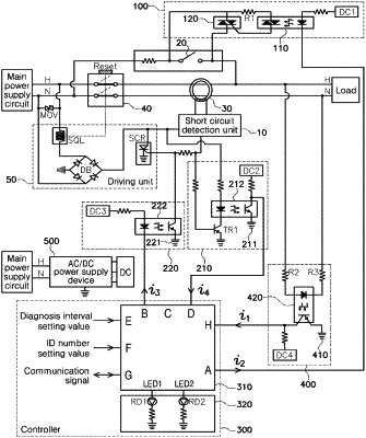
1. An automatically testable short circuit breaker, wherein the short circuit breaker comprises: power supply lines connected to a main power supply circuit; a test button configured to generate a short circuit current in the power supply lines, thereby checking an operating state of the short circuit breaker; a zero phase current transformer configured to detect the short circuit current between the power supply lines; a shut-off unit installed in the power supply lines, thereby performing functions of supplying and shutting off a power supply; a driving unit configured to control a power supply shut-off operation of the shut-off unit; and a short circuit detection unit configured to determine whether a short circuit current is generated from the zero current transformer, thereby generating a short circuit detection signal, the short circuit breaker further comprising:
a pseudo short circuit signal driving circuit unit connected to opposite ends of the test button, thereby generating, without having windings with respect to the zero phase current transformer, a pseudo short circuit signal giving the same effect as when the opposite ends of the test button are connected to each other;
a pseudo short circuit signal recognition circuit unit connected between the short circuit detection unit and the driving unit and configured to recognize the short circuit detection signal, thereby outputting a diagnosis signal;
a pseudo short circuit signal shut-off circuit unit connected between the pseudo short circuit signal recognition circuit unit and the driving unit and configured to induce the short circuit detection signal to grounding in a condition that the pseudo short circuit signal driving circuit unit operates, so that the short circuit detection signal is shut off without flowing into the driving unit; and
a controller configured not only to generate a driving signal giving the same effect as when the test button is pressed to the pseudo short circuit signal driving circuit unit so as to give the same effect as when the opposite ends of the test button are connected to each other but also to determine whether the short circuit breaker operates normally by receiving the diagnosis signal output from the pseudo short circuit signal recognition circuit unit.
|