| CPC F28F 21/062 (2013.01) [B01D 1/02 (2013.01); B01D 1/26 (2013.01); B01D 1/28 (2013.01); B01D 1/289 (2013.01); C02F 1/041 (2013.01); C02F 1/06 (2013.01); F04B 25/005 (2013.01); F04B 35/01 (2013.01); F04B 39/0094 (2013.01); F04B 39/12 (2013.01); F04B 45/02 (2013.01); F04B 53/144 (2013.01); F04D 25/088 (2013.01); F15B 15/10 (2013.01); F28B 1/06 (2013.01); F28D 1/024 (2013.01); F28D 1/0472 (2013.01); F28D 1/0477 (2013.01); F28F 3/06 (2013.01); F28F 3/14 (2013.01); F28F 21/065 (2013.01); C02F 2103/08 (2013.01); F28D 7/005 (2013.01); F28D 2021/0063 (2013.01)] | 20 Claims |
|
1. An air thermal conditioning system for at least one of heating air and cooling air, the air thermal conditioning system comprising:
a cross-flow heat exchanger array that includes:
a housing;
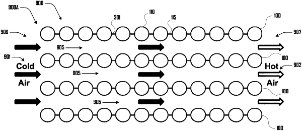
a plurality of at least 50 stacked planar membrane heat exchangers disposed in parallel and held in tension by the housing via respective opposing top and bottom ends of the respective planar membrane heat exchangers, the planar membrane heat exchangers stacked in parallel with a space separating each of the planar membrane heat exchangers, the space separating each of the planar membrane heat exchangers being an opening located centrally between the respective planar membrane heat exchangers that extends between the opposing top and bottom ends of the respective planar membrane heat exchangers and extends between opposing peripheral edges of the respective planar membrane heat exchangers, with each of the planar membrane heat exchangers comprising:
a first planar polymer sheet having a thickness between 0.1 mm and 0.05 mm, the first planar polymer sheet consisting essentially of a polymer;
a second planar polymer sheet having a thickness between 0.1 mm and 0.05 mm, the second planar polymer sheet coupled to the first planar polymer sheet at least by a welded seam, the second planar polymer sheet consisting essentially of the polymer; and
at least one fluid chamber defined by the first and second planar polymer sheets and the welded seam, with the at least one fluid chamber extending between the first and second ends and opening to a first and second port defined by the first and second planar polymer sheets at the top and bottom ends respectively; and
a first and second fluid conduit respectively disposed at and communicating with the first and second ports of the planar membrane heat exchangers, the first and second fluid conduits fluidically coupling the plurality of planar membrane heat exchangers and configured generate a fluid flow within the fluid chambers of the plurality of planar membrane heat exchangers, the fluid flow being the same direction for all of the plurality of planar membrane heat exchangers and comprising:
flowing into the first fluid conduit,
flowing between the top and bottom ends within the respective chambers, and
flowing out the second fluid conduit, with fluid flowing in and out of the first and second fluid conduits respectively on the same side of the cross-flow heat exchanger array.
|