| CPC F24F 11/42 (2018.01) [F24F 1/16 (2013.01); F24F 11/67 (2018.01); F25B 47/022 (2013.01); F24F 1/32 (2013.01); F25B 2313/0251 (2013.01); F25B 2313/0253 (2013.01); F25B 2313/02522 (2013.01); F25B 2313/02531 (2013.01); F25B 2313/02532 (2013.01); F25B 2313/02533 (2013.01); F25B 2313/0314 (2013.01); F25B 2313/0315 (2013.01); F25B 2347/021 (2013.01)] | 13 Claims |

|
1. An air-conditioning apparatus comprising:
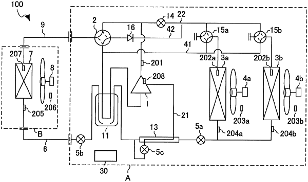
a refrigerant circuit including
a main circuit in which a compressor, a cooling/heating switching device, an indoor heat exchanger, a pressure reducing device, and parallel outdoor heat exchangers are connected by refrigerant pipes, and
a bypass circuit connected, by a pipe, to each of the parallel outdoor heat exchangers via a defrosting refrigerant pressure-reducing device, a defrosting flow passage switching device, and a backflow prevention device, the defrosting refrigerant pressure-reducing device being configured to reduce a pressure of refrigerant that branches off from the main circuit, by adjusting a flow rate of the refrigerant in a refrigerant pipe that branches off from a discharge pipe at the compressor, the defrosting flow passage switching device being configured to switch a flow passage for refrigerant that is supplied to one of the parallel outdoor heat exchangers, the backflow prevention device being provided between the defrosting flow passage switching device and the cooling/heating switching device to prevent backflow of low-pressure refrigerant that flows to a suction side of the compressor, the bypass circuit being configured to: cause part of refrigerant discharged from the compressor to branch off from the discharged refrigerant; switch a flow passage for use in introduction of refrigerant, using the defrosting flow passage switching device, to select one of the parallel outdoor heat exchangers as a defrosting target to be defrosted; and supply defrosting refrigerant whose pressure is reduced by the defrosting refrigerant pressure-reducing device to the defrosting target;
an air-conditioning load state detection unit configured to detect an air-conditioning load state;
an operation-state detection unit configured to detect an operation state of the refrigerant circuit; and
a controller configured to individually control operations of the compressor, the pressure reducing device, the defrosting refrigerant pressure-reducing device, and the defrosting flow passage switching device,
wherein the air-conditioning apparatus has a simultaneous heating and defrosting operation mode in which a heating operation and a defrosting operation are simultaneously performed such that while the heating operation is continued on an indoor side, the defrosting refrigerant is made to flow in the bypass circuit on an outdoor side to alternately defrost the parallel outdoor heat exchangers, and
in the simultaneous heating and defrosting operation mode, the controller controls the compressor, the pressure reducing device, and the defrosting refrigerant pressure-reducing device such that control amounts of the compressor, the pressure reducing device, and the defrosting refrigerant pressure-reducing device reach respective normal-time control target values set based on the air-conditioning load state and the operation state.
|