| CPC F16K 11/076 (2013.01) [F16K 5/0689 (2013.01); F16K 5/201 (2013.01); F16K 27/041 (2013.01)] | 15 Claims |

|
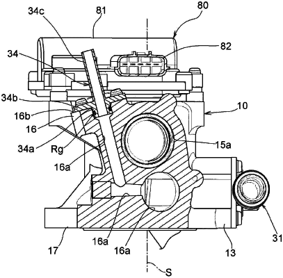
1. A rotary-type valve device, comprising:
a tubular valve that has an inner passage and opening parts that are opened in an outer circumferential wall from the inner passage toward an outward side in a radial direction, wherein each of the opening parts is formed as an oblong hole that is long in a circumferential direction around an axial line;
a housing that accommodates the tubular valve and supports the tubular valve such that the tubular valve is able to turn;
a tubular passage member that is assembled in the housing such that the tubular passage member abuts on the outer circumferential wall of the tubular valve and that defines a radial-direction passage; and
a biasing spring that biases the tubular passage member toward the outer circumferential wall,
wherein the tubular passage member comprises
an abutting member that abuts on the outer circumferential wall, and
an intervening member that has an annular pressing part intervening between the abutting member and the biasing spring and partially pressurizing the abutting member, and
the abutting member includes an annular sealing surface in a region that is aligned with the annular pressing part in a biasing direction of the biasing spring,
wherein the tubular valve selects whether or not to cause the inner passage to communicate with the radial-direction passage through rotating a position of the opening parts,
the abutting member comprises a small-diameter part that is fitted to an inside of the intervening member and a large-diameter part that defines an annular pressurized part directly pressurized by the annular pressing part, and
the intervening member comprises
a large-diameter inner circumferential surface to which the small-diameter part is fitted,
a small-diameter inner circumferential surface that defines the radial-direction passage, and
an annular step difference part that is formed between the large-diameter inner circumferential surface and the small-diameter inner circumferential surface, and
the abutting member comprises an annular end surface that is defined by the small-diameter part to face the annular step difference part in a non-contact manner,
wherein the annular pressing part, the annular pressurized part and the annular sealing surface are aligned in line on a straight line on which a bias force of the biasing spring acts.
|