| CPC F16D 65/10 (2013.01) [F16D 65/827 (2013.01); F16D 2065/136 (2013.01); F16D 2065/1316 (2013.01); F16D 2065/1328 (2013.01); F16D 2065/1392 (2013.01)] | 12 Claims |

|
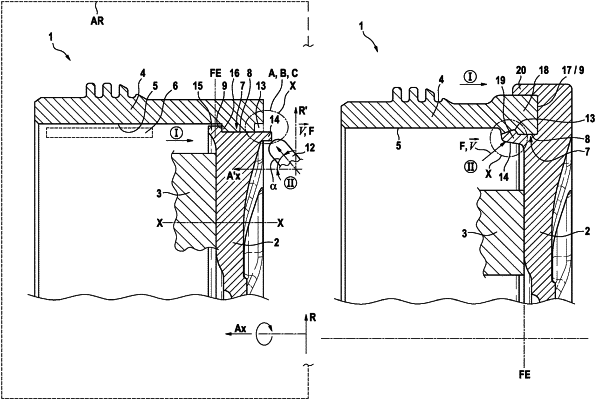
1. A manufacturing method for a pot-shaped composite brake rotor comprising:
forming at least one fixing element on a securing component;
defining a deformation zone on one of the at least one fixing element and a friction ring component;
defining a cavity on the other of the at least one fixing element and the friction ring component;
engaging a press-fit connection between the securing component and the friction ring component by axially moving at least one of the securing component and the friction ring component, wherein the press-fit connection rotationally fixes the securing component and the friction ring component to one another;
joining the securing component and the friction ring component with the at least one fixing element by forming the at least one fixing element in the deformation zone subsequent to engaging the press-fit connection;
one of: a pressing and a rolling process by one of: forcing a tool in a working chamber in a direction of a rotationally driven workpiece and forcing the workpiece in the direction of the tool; and
in the working chamber:
rotating the workpiece about a centrally arranged rotational axis parallel to the axial direction of the friction component and securing component for rotational movement;
mounting the tool in the working chamber to be movably guided in all directions; and
arranging the tool with defined spatial angle relative to the workpiece and physically orientable relative to the rotational axis.
|