| CPC F16C 3/023 (2013.01) [B60K 17/22 (2013.01); F16D 1/076 (2013.01); F16D 3/06 (2013.01); F16C 2226/80 (2013.01)] | 8 Claims |

|
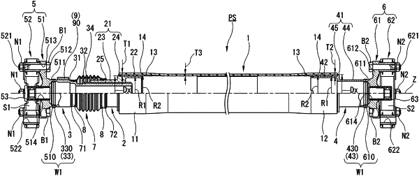
1. A power transmission shaft structured to be disposed between a first shaft and a second shaft being a pair of rotational shafts of a vehicle, the power transmission shaft comprising:
a shaft member that is shaped tubular, and includes a shaft first end and a shaft second end being a pair of ends in a direction of a rotational axis of the shaft member, wherein the shaft first end is directed toward the first shaft;
a connection tube including: an insertion section inserted in the shaft member via the shaft first end; a connection tube body disposed nearer to the first shaft than the insertion section; and an internal spline disposed inside the connection tube body;
a sliding unit including: an external spline inserted in the internal spline in order to establish spline coupling with the internal spline; and a sliding unit body shaped tubular, and connected to the external spline, and disposed nearer to the first shaft than the internal spline;
a joint unit that is structured to connect the sliding unit to the first shaft, and includes: a joint base section shaped annular and connected to the sliding unit body; and a first joint integrated with the joint base section and structured to be connected to the first shaft;
a boot that is shaped tubular, and overlaps with both of the connection tube body and the sliding unit body, and includes a boot first end and a boot second end being a pair of ends in the direction of the rotational axis, wherein: the boot first end is directed toward the first shaft, and is fixed to an outer periphery of the sliding unit body; and the boot second end is directed toward the second shaft, and is fixed to an outer periphery of the connection tube body; and
a weight member disposed between the boot first end and the first joint in the direction of the rotational axis, and mounted to the outer periphery of the sliding unit body by welding.
|