| CPC F02K 1/72 (2013.01) [F02K 1/763 (2013.01); F05D 2250/34 (2013.01); F05D 2260/50 (2013.01)] | 10 Claims |

|
1. A thrust reverser for an aircraft propulsion system, said thrust reverser comprising:
a fixed outer structure,
a movable outer structure,
at least one shutter flap comprising a rear end articulated on the movable outer structure, and
a control mechanism configured to make the thrust reverser switch between:
a direct thrust configuration wherein the movable outer structure is in a closed position and the at least one shutter flap is in a retracted position so as to channel a fluid flow in a conduit delimited radially outwards by the movable outer structure, and
a thrust reversal configuration wherein the movable outer structure is in an open position clearing a radial opening, and wherein the at least one shutter flap is in a deployed position so as to divert at least one portion of said fluid flow towards said radial opening,
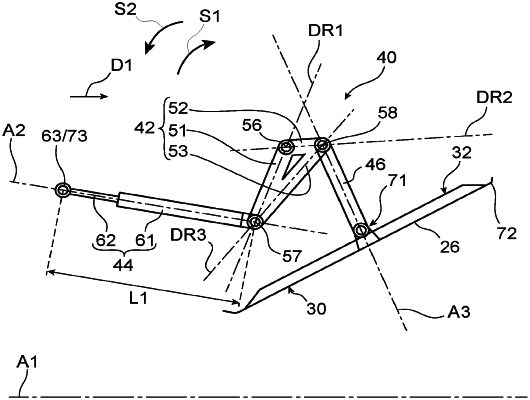
wherein the control mechanism comprises at least one transmission member including first, second and third sections connected together so as to form a triangle and extending respectively along first, second and third return directions secant to each other, the first and second sections forming a vertex comprising a first cooperation element, the first and third sections forming a vertex comprising a second cooperation element, and the second and third sections forming a vertex comprising a third cooperation element, the at least one transmission member being:
connected to the movable outer structure by a first articulation cooperating with said first cooperation element so as to enable a rotation of the at least one transmission member relative to the movable outer structure about an axis of rotation of said first articulation,
connected to the fixed outer structure by a first connecting member, the at least one transmission member being articulated to said first connecting member by a second articulation cooperating with the second cooperation element, the first connecting member being configured so as to move the at least one transmission member in rotation about the axis of rotation of the first articulation in a first direction when the movable outer structure is moved towards the open position and in a second direction when the movable outer structure is moved towards the closed position, and
connected to the at least one shutter flap by a second connecting member, the at least one transmission member being articulated to said second connecting member by a third articulation cooperating with the third cooperation element, the second connecting member being configured so as to move the at least one shutter flap towards the deployed position when the at least one transmission member is moved in said first direction and towards the retracted position when the at least one transmission member is moved in said second direction.
|