| CPC F02B 37/183 (2013.01) | 6 Claims |

|
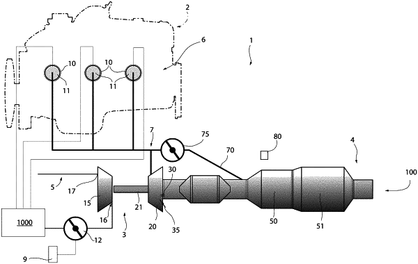
1. A drive assembly (1) for a motor vehicle, comprising:
an internal combustion engine (2) comprising, in turn, at least one intake duct (5), through which fresh air can flow, and at least one exhaust duct (7), through which a burnt air and gas mixture can flow;
a turbocharger (3) designed to supercharge said internal combustion engine (2); and
a catalysing system (4) arranged in series to said exhaust duct (7);
said turbocharger (3) comprising, in turn:
a compressor (15), which can be operated to increase the fresh air flow rate flowing, in use, through said intake duct (5); and
a turbine (20), which is operatively connected to said compressor (15), can be flown through by said mixture and is designed to drag the compressor (15);
said drive assembly (1) further comprising:
a first wastegate duct (30) interposed between said turbine (20) and said catalysing system (4); and
a first wastegate valve (35) designed to control said first wastegate duct (30);
said first valve (35) being movable between:
a first opening position, so as to convey a maximum flow rate of said mixture inside said first wastegate duct (30); and
a second closing position, so as to convey a minimum flow rate of said mixture inside said first wastegate duct (30);
said drive assembly (1) further comprising:
a second duct (70) interposed between said exhaust duct (7) and said catalysing system (4); and
a second bypass valve (75);
said second valve (75) being movable between:
a third position, in which it fluidly connects said exhaust duct (7) and said catalysing system (4) so as to convey said mixture along said second duct (70) bypassing, in use, the entire turbine (20) so as to heat said catalysing system (4); and
a fourth position, in which it fluidly isolates said second duct (70) from said exhaust duct (7);
said drive assembly (1) further comprising a control unit (110) programmed to control said first and second valve (35, 75) and to generate a first signal, when said internal combustion engine (2) is in a first condition, and a second signal, when said internal combustion engine (2) is in a second condition;
characterised in that said control unit (110) is programmed to detect the operating state of said engine (2) and to place:
said second valve (75) in said third position and said first valve (35) in said second position, in said first condition of said engine (2) and in case of a cold start of the engine (2);
said first valve and second valve (35, 75) in corresponding intermediate positions between said first and second position and said third and fourth position, in case, in use, said catalysing system (4) needs to be heated with said engine (2) already running;
said control unit (110) being further programmed to process a third signal associated with a simulated temperature of said catalysing system (4);
said control unit (110) being programmed to generate said first signal when said third signal is below a first threshold value and to generate said second signal when said third signal exceeds said first threshold value;
said drive assembly (7) further comprising a sensor (80) designed to detect a characteristic temperature (T) of said catalysing system (4);
said control unit (110) being further programmed to generate said first or second signal also based on the characteristic temperature (T).
|