| CPC F01D 5/225 (2013.01) [F01D 5/141 (2013.01); F01D 5/147 (2013.01); F05D 2220/40 (2013.01); F05D 2240/24 (2013.01); F05D 2240/30 (2013.01)] | 19 Claims |

|
1. A turbocharger turbine wheel comprising:
a hub that comprises a rotational axis, a backdisk and a nose, wherein the rotational axis defines an axial coordinate (z) in a cylindrical coordinate system that comprises a radial coordinate (r) and an azimuthal coordinate (θ) in a direction of intended rotation about the rotational axis; and
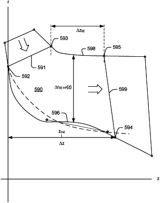
blades that extend outwardly from the hub, wherein each of the blades comprises a hub profile, a shroud edge, a leading edge, a trailing edge, a pressure side, and a suction side, wherein the hub profile comprises a global maximum radius and a global minimum radius, and wherein, between the global maximum radius and the global minimum radius, in an axial direction from the backdisk to the nose, the hub profile comprises a single local minimum radius at a first axial coordinate position and a single local maximum radius at a second axial coordinate position, wherein the first axial coordinate position is less than an axial coordinate position of a free tip of the leading edge of one of the blades, and wherein the second axial coordinate position is greater than the axial coordinate position of the free tip of the leading edge of the one of the blades.
|