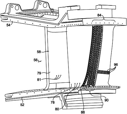
| CPC F01D 25/12 (2013.01) [F01D 5/187 (2013.01); F01D 9/041 (2013.01); F05D 2220/32 (2013.01); F05D 2230/21 (2013.01); F05D 2240/12 (2013.01); F05D 2260/201 (2013.01); F05D 2260/202 (2013.01)] | 12 Claims |

|
1. An airfoil for a land-based, industrial-use gas turbine engine, the airfoil comprising:
a leading edge;
a trailing edge having a length;
a pressure sidewall extending from the leading edge to the trailing edge, the pressure sidewall having a first edge along the trailing edge;
a suction sidewall extending from the leading edge to the trailing edge, the suction sidewall having a first edge along the trailing edge, wherein the pressure sidewall and the suction sidewall define a perimeter of the airfoil;
a cooling cavity defined between the pressure sidewall and the suction sidewall and positioned between the leading edge and the trailing edge, the cooling cavity having a supply opening at a radially outer portion of the airfoil for communicating a coolant into the cooling cavity;
a second cooling cavity defined between the pressure sidewall and the suction sidewall and positioned between the leading edge and the cooling cavity, the second cooling cavity having a second supply opening at the radially outer portion of the airfoil for communicating a coolant into the second cooling cavity;
a plurality of cooling apertures formed in at least one of the pressure sidewall and the suction sidewall proximate the leading edge, wherein the cooling apertures are adapted for expelling coolant received in the second cooling cavity out from the airfoil;
a rib wall extending between the pressure sidewall and the suction sidewall and from the top of the cooling cavity to the bottom of the cooling cavity, the rib wall separating the cooling cavity from the second cooling cavity;
an exit section defined between the pressure sidewall and the suction sidewall and positioned between the trailing edge and the cooling cavity;
a crossover wall extending between the pressure sidewall and the suction sidewall and from the top of the cooling cavity to the bottom of the cooling cavity, the crossover wall positioned at the forward end of the exit section and separating the cooling cavity from the exit section;
a plurality of crossover passages formed through the crossover wall;
a pin array positioned in the exit section adjacent the crossover wall;
the first edge of the suction sidewall and the first edge of the pressure sidewall converging into a unitary structure along the length of trailing edge; and
a plurality of exit ports formed via a post-casting process through the unitary structure and configured to communicate cooling air out of the airfoil.
|