| CPC E21B 47/002 (2020.05) [E21B 44/00 (2013.01); E21B 44/02 (2013.01); E21B 47/04 (2013.01)] | 25 Claims |

|
1. A method, comprising:
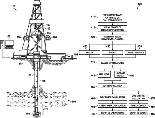
receiving input parameters at a casing wear processor that include downhole conditions of a borehole and at least one visual frame representing a digital image of a first drilling pipe segment of a drill pipe undergoing a trip out operation from the borehole subsequent to a drilling job, wherein the at least one visual frame is captured at a surface location of the borehole and a device capturing the visual frame is not in contact with the first drill pipe segment;
determining a depth range of the first drilling pipe segment, wherein the depth range corresponds to a location of the first drilling pipe segment in the borehole during the drilling job;
determining a surface change of a surface of the first drilling pipe segment by analyzing the at least one visual frame;
identifying a section of casing located downhole in the borehole, that was in contact with the first drilling pipe segment, utilizing the depth range;
determining a casing wear parameter by correlating the surface change to the section of casing utilizing the downhole conditions, a wear classification, and a metal wear of the first drilling pipe segment; and
replacing the section of casing or modifying a borehole operation of the borehole utilizing the casing wear parameter by using one or more of adjusting a weight-on-bit, a drill string rotation rate, a drill string size, a mud density, a mud rheology, a mud velocity, or a pipe eccentricity.
|