| CPC E21B 34/025 (2020.05) [E21B 21/106 (2013.01); F16K 1/422 (2013.01); F16K 1/465 (2013.01); F16K 27/02 (2013.01)] | 25 Claims |

|
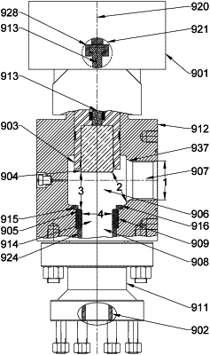
1. A choke system comprising:
a choke body including an input channel, a body channel, and an output channel;
a seat including a seat channel, the seat channel including an upper border and a lower border;
a gate having an upper border and a lower border, the lower border of the gate being configured to engage the seat when the gate is fully closed to block fluid flow through the seat channel;
a valve stem coupled to a top surface of the gate; and
a one-way seal between the seat and the choke body;
wherein (a) the body channel couples the input channel to the seat channel, and (b) the seat channel couples the body channel to the output channel;
wherein (a) the choke system is to convey fluid through the body channel and the seat channel when the gate is open and fluid is pressurized in the input channel, and (b) the choke system is to prevent conveyance of fluid through the body channel and the seat channel when the gate is closed and the gate contacts the seat;
wherein (a) the input channel includes an entry and an exit, the input channel exit being between the body channel and the entry of the input channel, (b) the entry of the input channel includes a first distance that is a maximum diameter of the entry of the input channel, the first distance being between 4.5 and 5.5 inches;
wherein (a) the exit of the input channel includes an upper border and a lower border, the lower border of the exit of the input channel being between the upper border of the exit of the input channel and the output channel, (b) a second distance is a minimum distance between the lower border of the exit of the input channel and the lower border of the gate when the gate is fully open, the second distance being greater than 3.75 inches;
wherein when the gate is fully open the lower border of the gate is a third distance from the upper border of the seat channel, the third distance being greater than 4.25 inches; and
wherein (a) the seat channel includes a fourth distance that is a maximum diameter of the seat channel and is between 3.6 and 4.4 inches, and (b) the upper border of the seat channel is between the valve stem and the lower border of the seat channel;
wherein the one-way seal is configured to allow fluid to flow from the output channel to the body channel but is further configured to disallow fluid to flow from the body channel to the output channel.
|