| CPC E21B 21/08 (2013.01) [E21B 2200/20 (2020.05)] | 6 Claims |

|
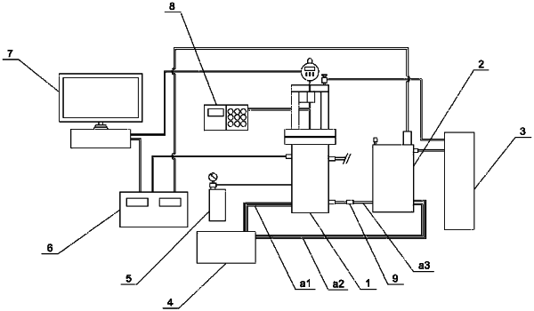
1. A drilling fluid inhibition evaluation device comprising a main test member, a gas source, a circulation heating system, a central control system and a computer, the main test member connected with the gas source, a first circulation pipeline in the circulation heating system circularly extending into the main test member, the main test member electrically connected with the central control system and the computer in turn; all a temperature control pressurization system, a confining pressure pump, an ultrasonic detector and a safety valve arranged outside of the main test member, the main test member connected with the confining pressure pump; a probe of the ultrasonic detector arranged within the main test member; the temperature control pressurization system arranged between the main test member and the gas source and connected with both the main test member and the gas source, and electrically connected with the central control system; the safety valve arranged on a direct connection pipeline that is formed between the temperature control pressurization system and the main test member;
the main test member comprising a pressure-bearing cup, a pressure-bearing bracket, a measuring rod, a rock sample cup shell and a dial indicator;
the pressure-bearing cup comprising a main cavity at an upper part thereof, and a temperature rising cavity at a bottom part thereof, a step-shaped inner-ring bulge arranged between the main cavity and the temperature rising cavity, a rock sample cup that is formed by the rock sample cup shell and a rock sample cup cover, placed on the inner-ring bulge, and a sample block arranged on the rock sample cup cover at the bottom of the rock sample cup;
the pressure-bearing bracket fixed above the pressure-bearing cup, a sealing ring arranged between the pressure-bearing cup and the pressure-bearing bracket, a supporting seat arranged at the top of the pressure-bearing bracket, a fixer arranged at a lower part of the supporting seat, and the dial indicator passing through the supporting seat to be in contact with a transmission block that is slidably connected with the inside of the fixer; and
the measuring rod vertically passing through a movable sealing block that completely seals a connection portion formed between the pressure-bearing cup and the pressure-bearing bracket, and then extending into the pressure-bearing cup, a bottom of the measuring rod clamped with an expansion piston above the sample block, and a top of the measuring rod in contact with a transmission block inside the fixer; and wherein
the pressure-bearing cup comprises a confining pressure head, a temperature measuring probe, an outlet valve and an inlet valve that pass through a cup wall thereof, all the confining pressure head, the temperature measuring probe and the outlet valve-arranged in the main cavity at the upper part of the pressure-bearing cup, and the inlet valve arranged in the temperature rising cavity at the bottom part of the pressure-bearing cup; wherein the confining pressure head is configured for connecting the external confining pressure pump and the inside of the pressure-bearing cup, the temperature measuring probe directly and electrically connected with the central control system and configured for reflecting the temperature inside the pressure-bearing cup to the central control system and the computer in real time; the liquid outlet valve arranged at the upper part of the pressure-bearing cup and connected with the main cavity and a liquid discharging external pipeline to conveniently discharge liquid; the inlet valve connected to the temperature rising cavity and the temperature control pressurization system, so that the liquid conveyed from the temperature control pressurization system is configured to directly supplement heat in the temperature rising cavity to result in facilitating to maintain the temperature of the experimental fluid and avoiding errors caused by temperature changes; and wherein
a confining pressure bag lined with steel wires is sleeved on an inner wall of the rock sample cup, the confining pressure bag passing through the rock sample cup shell and detachably connected with the confining pressure head through a confining pressure bag joint, and the confining pressure head connected with the confining pressure pump; and wherein
a telescopic supporting rod is connected above the measuring rod in a damping manner, and a fastening head arranged at a connection joint between the supporting rod and the measuring rod; an ultrasonic probe coaxially arranged inside the measuring rod and passing through the expansion piston to be in contact with the sample block, and then electrically connected with the external ultrasonic detector through a fastening block being arranged on a surface of the measuring rod; and wherein the ultrasonic detector is configured to monitor change characteristics of pore structures of rock samples in real time from a process that the experimental fluid contacts with the rock sample, to a process that the fluid permeates into the rock sample, and a subsequent expansion process, according to reflection conditions of sound waves.
|