| CPC B61D 27/0018 (2013.01) [B60H 1/00371 (2013.01)] | 14 Claims |

|
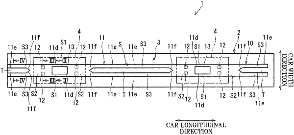
1. A railcar air conditioning duct which guides air fed from an air conditioner mounted on a railcar,
the railcar air conditioning duct comprising:
a duct wall forming an air flow passage which guides the air, fed from the air conditioner, in a car longitudinal direction; and
a plurality of through holes lined up in the car longitudinal direction, the through holes being open at a lower wall portion of the duct wall as air outlet ports through which the air in the air flow passage is blown from the air flow passage toward a passenger room, wherein:
a ratio of an opening area of one of the through holes to an area of one of a plurality of partial regions formed by dividing, in the car longitudinal direction, an inner surface of the lower wall portion such that in plan view, the partial regions contain the respective through holes falls within a range of 2.0% or more and 7.5% or less;
air receiving plates which are located in the air flow passage and receive the air flowing through the air flow passage in the car longitudinal direction project upward at opening edge portions of the respective through holes so as to be located at a far side from the air conditioner, and a top edge of each of the air receiving plates is a free edge;
an outer surface of the lower wall portion of the duct wall faces the passenger room in the railcar;
a groove extending in the car longitudinal direction is formed at an inner surface opposite to the outer surface of the lower wall portion;
the groove includes:
a pair of side walls opposed to each other in a car width direction, and
a bottom wall located between the inner surface and the outer surface of the lower wall portion in an upper-lower direction and connecting lower end portions of the pair of side walls;
and
the plurality of through holes are provided at the bottom wall of the groove.
|