| CPC B60K 6/387 (2013.01) [B60K 6/24 (2013.01); B60K 6/26 (2013.01); F16D 25/12 (2013.01); F16D 28/00 (2013.01); F16H 57/0415 (2013.01); F16H 57/0424 (2013.01); F16H 57/0473 (2013.01); F16H 57/0476 (2013.01); H02K 7/006 (2013.01); H02K 7/108 (2013.01); H02K 9/19 (2013.01); B60K 6/442 (2013.01); B60Y 2200/92 (2013.01); B60Y 2306/03 (2013.01); B60Y 2306/05 (2013.01); B60Y 2400/405 (2013.01); B60Y 2400/406 (2013.01); B60Y 2400/60 (2013.01)] | 17 Claims |

|
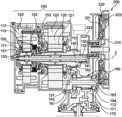
1. A drive unit for a drive train of an electrically drivable motor vehicle, the drive unit comprising:
a first electric machine having a rotor;
a second electric machine having a rotor;
an output shaft, the rotor of the second electric machine is connected to the output shaft for conjoint rotation therewith;
a separating clutch by which the rotor of the first electric machine is connectable to the output shaft for torque transmission;
a first flow system for implementing a flow of a first liquid for at least partial cooling of at least one of the first or second electric machines, wherein the first flow system is further configured such that the first liquid is fed through a line to the separating clutch for at least one of cooling or lubrication; and
a second flow system for implementing a flow of a second liquid, wherein the first flow system and the second flow system are configured such that heat from the first liquid in the first flow system is transferrable to the second liquid in the second flow system.
|