| CPC B60C 11/1259 (2013.01) [B60C 11/0302 (2013.01); B60C 2011/0341 (2013.01); B60C 2011/0365 (2013.01)] | 18 Claims |

|
1. A tire comprising:
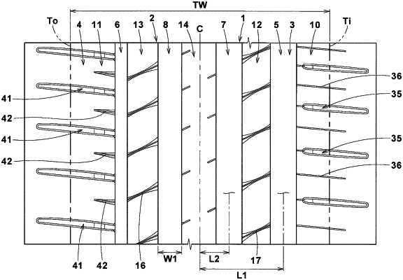
a tread portion having a designated mounting direction to a vehicle,
wherein the tread portion comprises an outer tread end located on an outer side of the vehicle when the tire is mounted to the vehicle, an inner tread end located on an inner side of the vehicle when the tire is mounted to the vehicle, four circumferential grooves extending continuously in a tire circumferential direction between the outer tread end and the inner tread end, and five land portions demarcated by the four circumferential grooves,
wherein the four circumferential grooves comprise an outer shoulder circumferential groove closest to the outer tread end when the tire is mounted to the vehicle,
wherein the five land portions comprise an outer shoulder land portion including the outer tread end, and an outer middle land portion adjacent to the outer shoulder land portion via the outer shoulder circumferential groove,
wherein the outer shoulder land portion has a greatest width, in a tire axial direction, of a ground contact surface among the five land portions,
wherein the outer shoulder land portion comprises a plurality of outer shoulder sipes connected to the outer shoulder circumferential groove,
wherein the outer middle land portion comprises a plurality of outer middle sipes connected to the outer shoulder circumferential groove,
wherein each of the outer shoulder sipes and the outer middle sipes comprises a pair of sipe walls,
wherein each of the outer shoulder sipes and the outer middle sipes comprises a body portion in which the pair of sipe walls are disposed substantially parallel to each other,
wherein a width of the body portion of each outer shoulder sipe is greater than a width of the body portion of each outer middle sipe,
wherein a maximum depth of each said outer shoulder sipe is greater than a maximum depth of each said outer middle sipe,
wherein the outer shoulder sipes extend from the outer shoulder circumferential groove at a first angle relative to the tire axial direction radial direction,
wherein the outer middle sipes extend from the outer shoulder circumferential groove at a second angle relative to the tire axial direction, and wherein the second angle is greater than the first angle,
wherein the outer middle sipes extend completely across the outer middle land portion in the tire axial direction, and each have a chamfered portion at at least one of sipe edges on both sides, and
wherein the chamfered portion of each said outer middle sipe has a minimum chamfered width at a position distant from circumferential edges on both sides of the outer middle land portion and has a chamfered width that increases from a position having the minimum chamfered width toward both the sides in the tire axial direction.
|