| CPC B41J 2/0459 (2013.01) [B41J 2/04541 (2013.01); B41J 2/04581 (2013.01)] | 8 Claims |

|
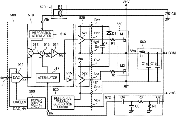
1. A liquid discharging apparatus comprising:
a drive signal output circuit outputting a drive signal that displaces between a first potential and a second potential that is lower than the first potential; and
a discharging portion including a piezoelectric element that is driven based on the drive signal and discharging liquid by a drive of the piezoelectric element, wherein
the drive signal output circuit includes
a modulation circuit that outputs a modulation signal obtained by modulating a base drive signal that is a base of the drive signal,
an amplification circuit that outputs an amplified modulation signal obtained by amplifying the modulation signal, and
a demodulation circuit that includes a first capacitor and a second capacitor and outputs the drive signal obtained by demodulating the amplified modulation signal,
the first potential is 25 V or higher,
the first capacitor and the second capacitor are coupled to each other in parallel,
a change rate of an electrostatic capacitance of the first capacitor when a direct-current voltage is supplied to the first capacitor is smaller than a change rate of an electrostatic capacitance of the second capacitor when the direct-current voltage is supplied to the second capacitor, and
an equivalent series resistance component of the second capacitor is smaller than an equivalent series resistance component of the first capacitor.
|