| CPC B26D 11/00 (2013.01) [B26D 1/085 (2013.01); B26D 1/30 (2013.01); B26D 1/305 (2013.01); B26D 3/08 (2013.01); B26D 3/085 (2013.01); B26F 1/18 (2013.01); B41J 11/70 (2013.01); B65H 18/103 (2013.01); B65H 20/02 (2013.01); B65H 35/06 (2013.01); B65H 37/04 (2013.01); B65H 39/16 (2013.01); B26D 2007/005 (2013.01); B65H 2301/5152 (2013.01); B65H 2403/5332 (2013.01); B65H 2701/12112 (2013.01); B65H 2701/18485 (2013.01)] | 3 Claims |

|
1. A printer comprising:
a thermal head configured to print a medium having a width;
a feeding roller configured to convey the medium located downstream, in a conveyance direction; and
a slit-cutting device located downstream, in the conveyance direction, of the feeding roller, wherein the slit-cutting device comprises:
a first holder comprising a first contactable member and a first surface configured to support the medium along the width of the medium;
a blade with a cutting edge, of a length between a first end of the blade and a second end of the blade, configured to contact the medium along a first direction, the first direction being parallel to the first surface and perpendicular to the conveyance direction;
a second holder configured to support the blade and configured to move relative to the first holder, the second holder comprising a second contactable member configured to contact the first contactable member; and
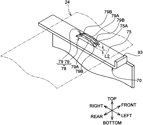
two parallel walls located on the first surface and spaced, via a second surface, from each other in the conveyance direction,
wherein a top surface of a central portion of each wall is parallel to the first surface,
wherein the second surface and the first contactable member are aligned in the first direction,
wherein the cutting edge is formed in a straight line,
wherein the two parallel walls extend in the first direction perpendicular to the conveyance direction for a distance less than the length of the cutting edge,
wherein the two parallel walls extend in the first direction perpendicular to the conveyance direction for a distance less than the width of the medium,
wherein the two parallel walls are spaced, in the first direction, from each of the first end of the cutting edge and the second end of the cutting edge,
wherein the cutting edge is located between the two parallel walls and configured to fully penetrate through a first portion of the medium spanning the two parallel walls in the first direction, when the second contactable member contacts the first contactable member, and
wherein the cutting edge, when the second contactable member contacts the first contactable member, is separated from the first surface by a distance greater than zero and is configured to not fully penetrate through a second portion of the medium located in the first direction relative to the first portion of the medium.
|