| CPC B25J 15/0616 (2013.01) [H02K 11/30 (2016.01); H02K 41/031 (2013.01)] | 6 Claims |

|
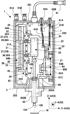
1. An actuator comprising:
a shaft;
a support part that rotatably supports the shaft;
a linear motion motor including a stator and a mover, movement of the mover in parallel with a central axis of the shaft relative to the stator of the linear motion motor causing the support part and the shaft to move in a direction of the central axis of the shaft;
a connecting member that is at least a part of a member connecting the mover of the linear motion motor and the support part;
a strain gauge provided in the connecting member to detect strain of the connecting member; and
a control device that controls the linear motion motor, based on the strain detected by the strain gauge,
wherein the connecting member includes a first member and a second member that are provided in a shifted manner in a direction of the central axis of the shaft, and
the strain gauge is provided on each of surfaces that are provided on the first member and the second member, respectively, the surfaces facing in the same direction and being parallel to each other and orthogonal to the central axis of the shaft.
|