| CPC A63B 24/0087 (2013.01) [A63B 21/0056 (2013.01); A63B 21/225 (2013.01); A63B 24/0062 (2013.01); G01L 3/22 (2013.01); H02K 7/104 (2013.01); H02K 49/043 (2013.01); H02P 3/12 (2013.01); H02P 15/00 (2013.01); A63B 2024/0093 (2013.01); A63B 2220/54 (2013.01); A63B 2220/833 (2013.01)] | 3 Claims |

|
1. A magnetic control device for directly sensing a motion load value applied to a fitness equipment, comprising:
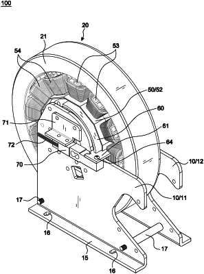
a supporting frame having a front frame body and a rear frame body fixed by multiple positioning rod, the supporting frame having a fixing base for fixing on the frame of the fitness equipment;
a flywheel having an outer ring body at an outer periphery of said flywheel and a wheel nave arranged at a center of said flywheel, the wheel nave having a shaft hole for setting the wheel nave on the shaft center, wherein the shaft center drives the flywheel to rotate;
a shaft center pivoted in a shaft hole of the wheel nave for receiving power transmitted by the fitness equipment;
a magnetic resistance mechanism, wherein the magnetic resistance mechanism includes a coil activity frame disposed in a surrounding relationship with the wheel nave and being active for making the magnetic resistance mechanism floatingly pivot relative to an inner periphery of the outer ring body of the flywheel, a stator arranged at the outer periphery of the coil activity frame inside the outer ring body of the flywheel and surrounded with multiple brake field cores, wherein the brake field cores have a containing space for arranging therein a magnetic coil, and an input line connected to the magnetic coil;
an action lever, wherein one end of the action lever is secured outside the magnetic resistance mechanism and is linked by a side edge thereof to the magnetic resistance mechanism, and wherein a pressure applied member is disposed at another end of the action lever;
a beam load cell secured to the supporting frame by a load cell bracket, wherein an outer end of the beam load cell is connected to the pressure applied member, and wherein an inner end of the beam load cell has a load signal output line for sending the motion load value;
a torque value conversion unit for converting the motion load value received by the beam load cell into a torque value; and
a control circuit unit arranged at a lateral side of the supporting frame, the control circuit unit including at least a micro processor control interface electrically connected to the torque value conversion unit, a power control unit, and a DC power supplier which connected to an AC power, wherein the control circuit unit is configured to input a desired torque value, and wherein the control circuit unit is electrically connected to the input line of the magnetic resistance mechanism and the beam load cell, wherein the control circuit unit generates a control signal to form an appropriate current after the control circuit unit calculates the desired torque value and inputs the appropriate current to the magnetic coil of the magnetic resistance mechanism, wherein the appropriate current in the magnetic coil subsequently generates an eddy current in the brake field cores, wherein the generated eddy current produces a resistance to the rotation of the flywheel, wherein the resistance subsequently drives the magnetic resistance mechanism to floatingly pivot relative to the inner periphery of the outer ring body of the flywheel, and wherein the resistance is applied to the beam load cell by the action lever, thus resulting in capturing a resistance value of the resistance by the control circuit unit, wherein the control circuit unit is further configured to compare the resistance value with the desired torque value, and to subsequently change the appropriate current supplied to the magnetic coil to result in attaining of an actual load corresponding to the desired torque value.
|