| CPC A62B 35/0068 (2013.01) [A62B 35/005 (2013.01); E06C 7/186 (2013.01); A62B 35/04 (2013.01); E06C 7/187 (2013.01)] | 19 Claims |

|
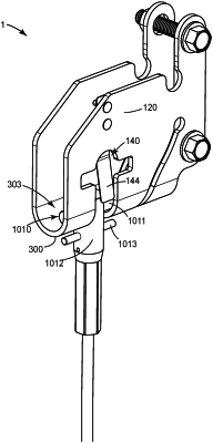
1. A top bracket for a vertical climbing fall protection system, the bracket exhibiting a vertical axis, a horizontally-oriented forward-rearward axis, and a horizontally-oriented lateral axis, and the bracket comprising:
at least one vertically-oriented base plate;
at least one vertically-oriented, pivotally deflectable plate that is configured to allow an upper end of a safety cable to be connected thereto;
wherein the at least one pivotally deflectable plate is integrally and pivotally connected to the at least one base plate by a vertically-oriented neck configured so that the pivotally deflectable plate extends at least generally forwardly from the base plate and so that the pivotally deflectable plate comprises an axis of pivotal deflection that passes through the neck and that is oriented at least generally parallel to the lateral axis of the top bracket;
wherein the top bracket further comprises a vertically-oriented abutment plate that extends forwardly from a lower section of the base plate and that comprises a forward abutment surface that is separated from a rearward abutment surface of the pivotally deflectable plate by an elongate gaps;
wherein the top bracket is configured to be attached to a secure support so that an upper end of a safety cable can be connected to the top bracket so that the top bracket supports the safety cable;
and,
wherein the abutment plate is positioned generally below, and rearward, of the pivotally deflectable plate and wherein the pivotally deflectable plate and the abutment plate are configured so that a sufficient downward force transmitted by the safety cable to the pivotally deflectable plate causes the pivotally deflectable plate to pivotally deflect generally downwardly and rearwardly into a deflected condition in which a width of the elongate gap between the rearward abutment surface of the pivotally deflectable plate and the forward abutment surface of the abutment plate is narrowed.
|